


Repeat this test with the shift levers in reverse and the engine
throttles at idle. Again, the starter should not engage for either
engine. If the starter for either engine engages with the shift
controls in any position other than the neutral position, then the
neutral safety switch is not functioning properly and you should
contact your dealer to have the neutral safety switch repaired by
a qualified marine mechanic before using the boat. If an engine
starts in gear during this test, immediately move the control
lever to the neutral position and turn the engine off.
IN SOME SITUATIONS, IT MAY BE POSSIBLE TO
ACCIDENTALLY START THE ENGINES IN GEAR
W I T H T H E T H R OT T L E S A B O V E I D L E I F T H E
NEUTRAL SAFET Y SWITCH IS NOT OPERATING
PROPERLY. THIS WOULD CAUSE THE BOAT TO
A CC E L E R AT E U N E X P E C T E D LY I N F O R WA R D
OR REVERSE AND COULD RESULT IN LOSS OF
CONTROL, DAMAGE TO THE BOAT, OR INJURY
TO PASSENGERS. ALWAYS TEST THE NEUTRAL
SAFETY SWITCH PERIODICALLY AND CORRECT
ANY PROBLEMS BEFORE USING THE BOAT.
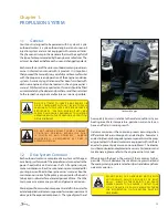
2.4
Engine Power Tilt and Trim
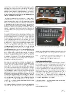
All outboard engines have a tilt and trim feature. Most outboard
engines have tilt/trim switches built into the engine shift and
throttle controls that allow the operator to control the position of
the outboards from the helm. Typically, a switch or switches on
the port control lever grip activates the tilt/trim for the engines.
Some engine controls have two switches on the control cover
to activate each engine individually.
Moving the outboard closer to the boat transom is called trim-
ming “in” or “down.” Moving the outboard further away from
the boat transom is called trimming “out” or “up.” In most
cases, the boat will run best with the outboard adjusted so the
hull will run at a 3 to 5 degree angle to the water.
The term “trim” generally refers to the adjustment of the
outboard within the first 20
o
range of travel. This is the range
used while operating your boat on plane. The term “tilt” is
generally used when referring to adjusting the outboard further
up for shallow water operation or trailering. For information
on the proper use and maintenance of the power tilt and trim,
please refer to the engine owner’s manual.
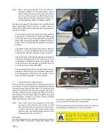
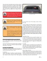
The stern wave gate must in the open or down position before
tilting the engines to the full up or trailering position. If the
wave gate is in the up position when the engines are tilted, the
cowlings will hit it causing damage to the engine cowlings
and wave gate. Always make sure the wave gate is down be-
fore tilting the engines and returned to the up position before
operating the boat.
THE ENGINE COWLINGS WILL HIT THE WAVE GATE
WHEN THE ENGINES ARE TILTED TO THE FULL
UP OR TRAILERING POSITION. THIS CAN CAUSE
SEVERE DAMAGE TO THE ENGINE COWLINGS AND
WAVE GATE. ALWAYS MONITOR THE ENGINES
AS THEY TILT AND FOLD DOWN THE WAVE GATE
BEFORE TILTING THE ENGINES TO THE FULL UP
POSITION.
T H E E N G I N E H O S E S A N D C A B L E S O R T H E
TRANSOM GEL COAT CAN BE DAMAGED BY TILTING
THE ENGINES TO THE FULL UP POSITION WITH
THE ENGINES TURNED TO THE WRONG POSITION.
M O S T B OATS R E Q U I R E T H E S T E E R I N G W H E E L
TO B E T U R N E D CO M P L E T E LY TO S TA R B OA R D
B E F O R E T I LT I N G T H E E N G I N E S TO T H E F U L L
UP POSITION. YOU SHOULD MONITOR EACH
ENGINE AS IT TILTS TO DETERMINE BEST FULL
TILT ENGINE POSITION FOR YOUR BOAT.
S O M E AU TO P I LOT S H AV E E N G I N E P O S I T I O N
SENSORS THAT ARE MOUNTED TO THE HYDRAULIC
STEERING CYLINDER. WITH THESE AUTOPILOTS,
T H E E N G I N E P O S I T I O N S E N S O R B R A C K E T
COULD HIT THE TRANSOM WHEN THE ENGINES
A R E T I LT E D TO T H E F U L L U P P O S I T I O N A N D
CAUSE DAMAGE TO THE ENGINE RIGGING, THE
AUTOPILOT OR THE TR ANSOM. IF YOU HAVE
AN AUTOPILOT INSTALLED ON YOUR BOAT, YOU
SHOULD MONITOR THE LOCATION OF THE ENGINE
C A B L E S A N D AU TO P I LOT B R A C K E T S A S T H E
ENGINES ARE TILTED TO DETERMINE THE BEST
ENGINE POSITION AND MAXIMUM ENGINE TILT
FOR YOUR APPLICATION.
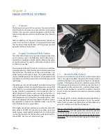
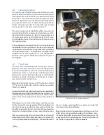
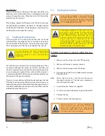
2.5
Engine Stop Switch
Your boat is equipped with an engine stop switch and lanyard.
When the lanyard is pulled it will engage the switch and shut
off the engines. We strongly recommend that the lanyard be
attached to the driver whenever the engines are running. If
an engine will not start, it could be because the lanyard is not
properly inserted into the engine stop switch. Always make
sure the lanyard is properly attached to the engine stop switch
before attempting to start the engines.
Refer to the engine
owner’s manual for
more information
on the engine stop
switch.
Engine Stop Switch
Summary of Contents for 262 Abaco
Page 1: ... Owner s Manual 262 Abaco Scout Boats Inc 2531 Hwy 78 West Summerville SC 29483 ...
Page 2: ... THIS PAGE WAS LEFT BLANK INTENTIONALLY Print Date 6 2007 Current ...
Page 4: ... THIS PAGE WAS LEFT BLANK INTENTIONALLY ...
Page 6: ... THIS PAGE WAS LEFT BLANK INTENTIONALLY ...
Page 10: ...10 THIS PAGE WAS LEFT BLANK INTENTIONALLY ...
Page 30: ...30 THIS PAGE WAS LEFT BLANK INTENTIONALLY ...
Page 40: ...40 THIS PAGE WAS LEFT BLANK INTENTIONALLY ...
Page 46: ...46 THIS PAGE WAS LEFT BLANK INTENTIONALLY ...
Page 52: ...52 THIS PAGE WAS LEFT BLANK INTENTIONALLY ...
Page 64: ...64 THIS PAGE WAS LEFT BLANK INTENTIONALLY ...
Page 70: ...70 THIS PAGE WAS LEFT BLANK INTENTIONALLY ...
Page 91: ...91 Appendix A SCHEMATICS Main Harness ...
Page 92: ...92 Battery Select Panel ...
Page 93: ...93 Battery Select Panel Wiring ...
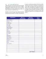
Page 104: ...104 Appendix C MAINTENANCE SCHEDULE AND LOG ...
Page 105: ...105 MAINTENANCE LOG Hours Date Dealer Service Repairs ...
Page 106: ...106 MAINTENANCE LOG Hours Date Dealer Service Repairs ...
Page 107: ...107 MAINTENANCE LOG Hours Date Dealer Service Repairs ...
Page 108: ...108 MAINTENANCE LOG Hours Date Dealer Service Repairs ...
Page 109: ...109 MAINTENANCE LOG Hours Date Dealer Service Repairs ...
Page 113: ...113 THIS PAGE WAS LEFT BLANK INTEN TIONALLY ...
Page 119: ...119 ...
Page 120: ...120 Scout Boats Inc 2531 Hwy 78 West Summerville SC 29483 ...