background image

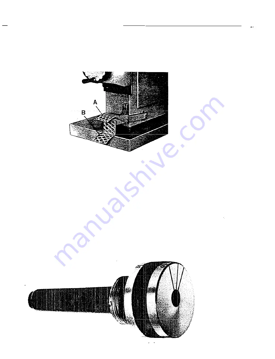
To  release  the  pedal  allowing  the  head  to  lift  off  again.  it  is  necessary 

to  press  the  red  upper  pedal  (A). 

N.B.  PEDALS  ARE  TO  BE  USED  ONLY  WHEN  THE  MACHINE  IS  RUNNING. 

Fig.  9 

j)  BALANCING  OF  ECCENTRIC  CHUCKS  (fig.  10) 

The  balancing  of  the  eccentric  chuck  is  effected  as  follows: 

a)  Mount  tile  cutter  and  collet  in  the  chuck  with  the  cutting  edge  between 

the  two  lines  marked  on  the  face  of  the  same.  The  angle  formed  by 

the  cutting  edge  with  the  line  marked  " 0,,  on  the  chuck.  gives  the 

dimensions  of  the hole in  compliance  with  the  eccentricity  of the  chuck 

and  the  diam  of  the  cutter.  To  obtain  the  required  milling  diam.  it  is 

necessary .to  consult  the  table. 
For  instance:  having  a  8  mm  diam.  hole  to  execute;  a  chuck;  n. 

and 

6.5 

mm.  diam.  cutter.  According  to  the  table,  the  angle  that  the 

cutter  has  to  perform  with  the  line  marked  with  a 

,,0. 

is  47". 

Fig.  10 

Summary of Contents for K8

Page 1: ...semi CORPORATION 59 3 f E CHTREE INO BLVD SUITE A NORCAOSS GA lr g o l 446 1120 ...

Page 2: ... Iy as an exemplification SCM reserves the right to introduce at any time v ariations and modifications Features and descriptions included here are actual during the approval of this operation and maintenance hand book for the pri nt SCM reserves the right to su spend at any moment and without obligation to inform the production of some mOdels and the changing of features of drawings and of the su...

Page 3: ...de pin g Use of the air lift pedal h Use of the mechanical pedal i Balancing of eccentric chucks I Change of speed m Mechanical brake n Belt tension 0 How to get rid of the most common inconveniences a Every week b Every month II MAINTENANCE c Every three months d Suggested lubricants e Lubrication and cleaning III REPLACEMENT OF SPARE PARTS a Replacement of the ball bearings Pag 3 3 3 4 4 5 6 7 8...

Page 4: ...of adjustable depth settings Work table size Max passage between table and spindle Max height of table from ground Vertical movement of spindle Guide pins with 5 positions and six diam Overall dimensions Net weight III EOUIPMENT Every machine is equipped with 29 1 2 750 mm 10 000 20 000 R P M 3 4 5 HP 5 5 HP 4 102 mm 6 35 5 8 x30 5 16 905x770 mm 12 1 4 310 mm 40 15 16 1040 mm 7 7 8 200 mm 3 16 to ...

Page 5: ...r minals A of the junction box located at the left of the machine whilst the terminal B is to be connected to the ground of the in stallation Check immediately the direction of rotation of the spindle which must be clockwise If rotation is incorrect reverse two wires without mo ving the earth connection For machines equipped with eletromagnetic starters before operating the switch press the push b...

Page 6: ...ne junction C The working pressure is to be at least 6 atm 88 2 p s i The diagrams of the pneumatic installations are those of fig 23 for machines with air power head lifting and of fig 24 for machines with pneumatic lifting and automatic opening of copying device feed rollers Fig ...

Page 7: ...is fully lifted Insert the pin A in the hole of the machine s head Remove the chuck 8 Insert the collet e Slightly screw the chuck 8 on the spindle D Introduce the tool E in its housing Tighten the chuck 8 by means of the 36 mm 1 3 8 wrench F Remove the pin A Fig 5 ...

Page 8: ...ing the spindle descent locking screw fig 7J Loosen the counternut A Rotate the screw BJ as much as required Tighten the counternut A completely 3 Operating the screws of the revolver C fig 7J This adjustment is principally used when on the same workpiece it is necessary to work successively at two different depth or more The position of the revolving drum are six in all If a determinate type of j...

Page 9: ...the tool can be lowered or lifted to try eventual positions When the pedal is pushed down completely to the release the permanent position of the lowered tool is ob tElined 2 The lowering speed of the tool can be controlled by oper8ting thp adjustment knob A whilst the knob B adjusts the lifting speed Fig 8 h USE OF THE MECHANICAL PEDAL fig 9 The double pedal is American type with positive i ction...

Page 10: ... the cutting edge between the two lines marked on the face of the same The angle formed by the cutting edge with the line marked 0 on the chuck gives the dimensions of the hole in compliance with the eccentricity of the chuck and the diam of the cutter To obtain the required milling diam it is necessary to consult the table For instance having a 8 mm diam hole to execute a chuck n 2 and a 6 5 mm d...

Page 11: ...0 32 11 24 48 32 5 11 24 39 33 12 24 52 33 5 12 24 52 34 12 24 45 34 S 12 24 11 3 8 5 40 23 7 18 51 35 12 126 11 5 3 9 38 23 S 7 18 45 35 S 12 12 3 9 5 40 24 8 18 49 36 12 12 5 3 10 37 24 S 8 18 42 36 S 13 13 3 10 5 40 25 8 19 49 37 13 IJ CHANGE OF SPEED fig 1 1J Is effected operating the switch lever AJ 1J On the position the speed is 10 000 rpm 2J On the position 2 the speed is 20 000 rpm mJ MEC...

Page 12: ... its tension after one day s work N B Whenever the belt tension is adjusted also check that it runs in the pulley s center If not this would mean that the motor is not more parallel to the spindle In this case as shown in fig 14J 1 Loosen the counternuts A 2 Tighten or untighten the adjustment screws B until the belt runs in the centre of the pulley 3 Tighten the counternuts holding the adjustment...

Page 13: ...rong mounting 01 the lilt ing cylinder s shalt Alignment between spindle and motor not correct The lifting and lowering 01 the spindle is too speedy Pulleys clogged SOLUTIONS Make sure that the voltage of motor effectively corre sponds to the mains Make sure that there is no voltage drops on the line over 10 volt Adjust the belt tension fig 13 par Itnu Remove the p iey and dirt Check il current re...

Page 14: ...crew and the handwheel pivot Lubricate the mechanical pedal s movements c Every three months 480 hours For the 10 000 rpm speed lubricate the head ball bearings fig 15 N B If the above rules are followed very closely and the machine is always kept well lubricated and clean the ball bearings will last for an exceptionally long time and the machine will always work perfectly and without any vibratio...

Page 15: ...e gr J Jsed whenever they overheat For this operation it is suggested to use the special ESSO BEACON 325 grease for high speed ball bearings 2 Cylinder jacket fig 16 Is to be lubricated with normal Stauffer grease by filling and then by squeezing the lubricator A CAUTION when the machine is still cold the cylinder s friction is over normal values but after approximately ten minutes running it beco...

Page 16: ...move the bush A fig 19 7 Take off the grease retaining cap B fig 19 make eventually use of two screw drivers 8 Remove the circlip C fig 19 by means of appropriate pincers and take off the spindle from the bottom 9 Remove the ball bearings and pay attention to their correct position for the re mounting In case a ball bearing is to be used again after its extraction ope rate with precaution only aga...

Page 17: ... b Jj _____1 1 _ r I j __ L ...

Reviews: