11
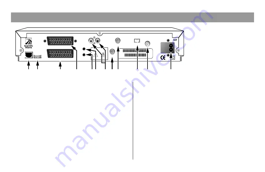
Understanding the Back Panel
Note:
The back panel of your
DHCT may vary slightly
from this diagram.
1
Ethernet
Connect an Ethernet-equipped
computer, optional
2
USB
Connect to external equipment
(Universal Serial Bus)
3
VCR
Connect to a SCART-equipped VCR
4
TV
Connect to a SCART-equipped TV
5
IR Blaster Out
Connect optional external remote
control or IR input device
6
IR Remote In
Connect to external IR receiver
7
Audio (L/R)
Connect to left/right audio inputs of
a stereo receiver or a TV with stereo
sound
8
Antenna
Connect terrestrial aerial
9
To TV
Connect to RF input of TV or VCR
10
Bypass
Connect an optional RF Bypass module
11
Cable In
Connect to cable signal from cable
service provider
12
AC Mains Inlet
Connect the DHCT to a mains outlet
L
R
IR BLASTER OUT
IR REMOTE IN
TO TV
AUDIO
VCR
95-240V ~
50-60Hz 25W
TV
RISK OF ELECTRICAL SHOCK
DO NOT OPEN
AVIS: RISQUE DE CHOC
ELECTRIQUE - NE PAS OUVRIR
CAUTION
ANTENNA
CABLE IN
BYPASS
ETHERNET
USB
RF MAC 0001A6C3575A
SA S/N SABDRPLKP
T9689
1
2
9
11
12
10
3
7
8
5 6
4


