


Assembly
18
03.00 | NSL3 | VERO-S quick-change pallet system | en | 1155408
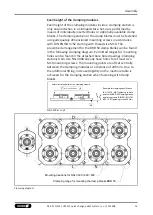
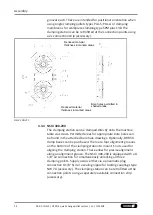
4.2 Aligning the clamping station
The clamping station can be aligned with loose T-nuts along an
aligning groove on the machine table. At least two T-nuts offset
lengthwise are provided and their size is matched to the aligning
groove on the machine table. The T-nuts are not included in the
scope of delivery of the clamping station.
Alignment using T-nuts
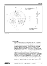
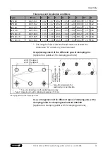
4.3 Mounting and connecting the clamping station
Flatness and distances
In order to assemble the clamping station, the clamping surface
must have a flatness of ≤ 0.03 mm (based on the entire support
areas of the clamping station). The clamping zone must have
sufficient rigidity in order to ensure the relative flatness of the
clamping modules. If several clamping stations are interlinked,
make sure that the flatness and height deviation of the locating
surfaces between modules (based on a 200 mm gauge for bore
holes) is ≤ 0.03 mm. The gauge deviation between the separate
clamping stations must not exceed ± 0.015 mm from module to
module.
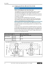
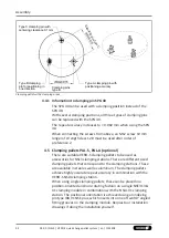
Redundancy
For the sake of conformity, clamping pins with positioning
accuracy in one direction (SPB 40) should be used for clamping
modules inside a clamping station or multiple linked clamping
stations that are more than 160 mm apart or that do not show a
positioning tolerance of ± 0.01 mm. For the clamping areas that
are not intended for aligning the device or pallet, clamping pins
with centering clearance (SPC 40) can be used (also refer to
chapter "Clamping pins"
).


