Assembly
02.00|ROTA NCA |en
33
necessary, align at the outer diameter with gentle taps using a
hammer.
8 Tighten the fastening screws (item 10) with a torque wrench.
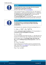
The breakaway torques
9 Check the chuck again for concentricity and axial run-out
accuracy (see Fig. "Lathe chuck assembly" - E
). The "Concentricity and axial run-out tolerances"
table shows the concentricities and axial run-out accuracies to
be achieved.
10 Check the actuating force is functioning and is sufficient.
11 Check the jaw stroke of the base jaws. (Item 2) Fasten the top
jaws marked 1, 2 and 3 to the base jaws using T-nuts (item 27)
and screws (item 26).
The spindle is disassembled in the same way but in the reverse
order.
Concentricity and axial run-out tolerances
Chuck size [mm]
Max. concentricity
error [mm]
Max. axial run-out
error [mm]
160
0.01
0.01
200
0.02
225
280
0.03
0.02
330


