background image

3

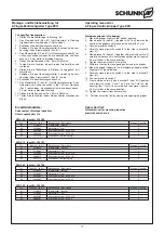
Montage- und Betriebsanleitung für
3-Finger-Zentrischgreifer Type PZH

Operating manual for
3-Finger-Centric-Gripper Type PZH

1.

Safety

1.1

Symbol key

This symbol is displayed wherever there is a
danger of injury or where the gripper may suffer
damage.

1.2

Appropriate use

The unit was designed for gripping and temporary secure holding
of workpieces or other objects.
The gripper is intended for installation / mounting for machinery
and equipment. The requirements of the applicable directives
must be observed and complied with.
The gripper may only ever be employed within the restrictions of
its technical specifications.
Using the system with disregard to even a minor specification will
be deemed inappropriate use. The manufacturer assumes no lia-
bility for any injury or damage resulting from inappropriate use.

1.3

Environmental and operating conditions

Use the unit only within the application parameters defined in
the Technical Catalog. The most recent version applies
(according to the General Terms and Conditions). Please
make sure that your application has been checked based on
the current SCHUNK calculation program. If this is not the
case, we can provide no warranty.

Standard for quality of the compressed air according to ISO
8573-1: 6 4 4.

Clean ambient conditions at room temperature are required.
If these conditions are not ensured, the maintenance interval
will be shorter, depending on the actual utilization.

The environment must be free of splashing water and vapors,
and also of abrasive dust and process dust. This does not
apply to units designed especially for dirty environments.

1.4

Safety information

1. The gripper is built according to the level of technology avai-

lable at the time of delivery and is safe to operate. However,
the gripper may still be dangerous if, for example:
the gripper is used, assembled or maintained inappropriately
or is used for purposes other than those it is intended for.
the EC Machine Directive, the accident prevention regu-
lations, the VDE guidelines, or the safety information and
assembly instructions are not heeded.

2. Any persons who may be responsible for assembly, commis-

sioning and maintenance of the unit are obliged to have read
and understood all of the operating instructions, in particular
chapter 1 “Safety”. We recommend that the customer have
this confirmed in writing.

3. The installation, deinstallation, assembly of all motion detec-

tors, connection and commissioning may only be performed
by authorized, appropriately trained personnel.

4. Modes of operation that adversely affect the function and/or

the operational safety of the gripper are to be refrained from.

5. Never move any parts by hand as long as the power

supply is connected.

6. Never grasp into uncovered mechanisms and never

grasp between the gripper fingers.

1.

Sicherheit

1.1

Symbolerklärung

Dieses Symbol ist überall dort zu finden wo
besondere Gefahren für Personen oder Beschädi-
gungen des Greifers möglich sind.

1.2

Bestimmungsgemäßer Gebrauch

Das Greifmodul wurde konstruiert zum Greifen und zeitbegrenz-
ten sicheren Halten von Werkstücken bzw. Gegenständen.
Das Produkt ist zum Ein-/Anbau für Maschinen bzw. Anlagen
bestimmt. Die Anforderungen der zutreffenden Richtlinien müs-
sen beachtet und eingehalten werden.
Das Produkt darf ausschließlich im Rahmen seiner technischen
Daten verwendet werden.
Ein darüberhinausgehender Gebrauch gilt als nicht bestim-
mungsgemäß. Für Schäden aus einem solchen Gebrauch haftet
der Hersteller nicht.

1.3

Umgebungs- und Einsatzbedingungen

Die Einheit nur innerhalb der im Technischen Katalog defi-
nierten Einsatzparameter einsetzen. Es gilt jeweils die letzte
Fassung (lt. Kapitel 2.3 AGB). Bitte prüfen Sie, ob Ihr
Einsatzfall anhand des aktuellen SCHUNK-Berechnungs-
programms geprüft wurde. Ist dies nicht der Fall, kann keine
Gewährleistung übernommen werden.

Anforderung an die Druckluftqualität nach ISO 8573-1: 6 4 4.

Vorraussetzung sind saubere Umgebungsbedingungen bei
Raumtemperatur. Sollte dies nicht eingehalten werden, ver-
ringert sich je nach Anwendungsfall das Wartungsintervall.

Die Umgebung muss frei von Spritzwasser und Dämpfen,
sowie von Abriebs- oder Prozessstäuben sein. Ausgenom-
men hiervon sind Einheiten, die speziell für verschmutzte
Umgebungen ausgelegt sind.

1.4

Sicherheitshinweise

1. Der Greifer ist nach dem Stand der Technik zum Zeitpunkt

der Auslieferung gebaut und betriebssicher. Gefahren kön-
nen von ihm jedoch ausgehen, wenn z.B.:
der Greifer unsachgemäß eingesetzt, montiert, gewartet oder
zum nicht bestimmungsgemäßen Gebrauch eingesetzt wird.
die EG-Maschinenrichtlinie, die UVV, die VDE-Richtlinien, die
Sicherheits- und Montagehinweise nicht beachtet werden.

2. Jeder, der für die Montage, Inbetriebnahme und Instand-

haltung zuständig ist, muss die komplette Betriebsanleitung,
besonders das Kapitel 1 »Sicherheit«, gelesen und ver-
standen haben. Dem Kunden wird empfohlen, sich dies
schriftlich bestätigen zu lassen.

3. Der Ein- und Ausbau, die Montage der Näherungsschalter,

das Anschließen und die Inbetriebnahme darf nur von auto-
risiertem Personal durchgeführt werden.

4. Arbeitsweisen, die die Funktion und Betriebssicherheit des

Greifers beeinträchtigen, sind zu unterlassen.

5. Keine Teile von Hand bewegen, wenn die Energie-

versorgung angeschlossen ist.

6. Nicht in die offene Mechanik und zwischen die

Greiferfinger greifen.

Summary of Contents for PZH 140

Page 1: ... com USA SCHUNK Intec Inc Tel 1 919 572 2705 Fax 1 919 572 2818 info us schunk com www us schunk com HUNGARY SCHUNK Intec Kft Tel 36 46 50900 7 Fax 36 46 50900 6 info hu schunk com www hu schunk com INDIA SCHUNK India Branch Office Tel 91 80 40538999 Fax 91 80 41277363 info in schunk com www in schunk com ITALY SCHUNK Intec S r l Tel 39 031 4951311 Fax 39 031 4951301 info it schunk com www it schu...

Page 2: ...mbly 5 5 1 Befestigung des Greifers Fastening of the gripper 5 6 Luftanschluss Air connection 5 7 Problemanalyse Trouble shooting 6 8 Wartung und Pflege Maintenance and care 6 8 1 Wartungs und Pflegeintervalle Maintenance intervals 6 8 2 Zerlegen des Greifers ohne Greifkraftsicherung Disassembly of the gripper without Gripping force safety device with springs 7 9 Zusammenbauzeichnung Assembly draw...

Page 3: ...he function and or the operational safety of the gripper are to be refrained from 5 Never move any parts by hand as long as the power supply is connected 6 Never grasp into uncovered mechanisms and never grasp between the gripper fingers 1 Sicherheit 1 1 Symbolerklärung Dieses Symbol ist überall dort zu finden wo besondere Gefahren für Personen oder Beschädi gungen des Greifers möglich sind 1 2 Be...

Page 4: ...ingungen AG B Diese finden Sie auf unserer Webseite www de schunk com unter Service bei den Verkaufs und Lieferbedingungen Die Einheit gilt dann als defekt wenn deren Grundfunktion Greifen oder Schwenken nicht mehr gegeben ist 7 Always disconnect the power supply lines during assembly conversion maintenance and setting work 8 Always carry out maintenance work conversions and attachments outside of...

Page 5: ...ir borne noise emitted by the gripper is 70 dB A 5 Assembly CAUTION Before starting assembly of the gripper the power supply must be switched off Please also consider the safety hints on page 3 and 4 5 1 Fastening of the gripper 1 Fix the gripper with both fixing bores Two cylinder pins are enclosed to every shipment 2 Fasten the gripper in the 3 provided fastening bores 6 Luftanschluss ACHTUNG Be...

Page 6: ...nspection Gripper is not efficient Loss of pressure Check the sealings Check the pressure of the air feedings The gripper does not move the full stroke Dirt between the cover plate piston and base jaw 8 Maintenance and care CAUTION Please consider the safetey notes on pages 3 and 4 8 1 Maintenance intervals Greifer AUF Greifer ZU Schlauchloser Direktanschluss AUF Schlauchloser Direktanschluss ZU P...

Page 7: ...os 1 geschoben werden ACHTUNG Finger sind in das Gehäuse eingepasst und müssen beim Zusammenbau des Greifers in die jeweilige ursprüngliche Nut zurückgeschoben werden 13 Das Fixierstück Pos 2 aus dem Gehäuse Pos 1 ziehen 14 Die Gewindestifte Pos 36 vollständig herausdrehen 15 Die Zylinderstifte Pos 61 aus dem Fixierstück Pos 2 schieben 16 Kolbenstangen Pos 4 vorsichtig aus dem Fixierstück Pos 2 he...

Page 8: ...chgreifer Type PZH Operating manual for 3 Finger Centric Gripper Type PZH 41 9 43 12 8 15 10 32 11 60 44 31 62 1 33 2 24 3 30 70 4 39 25 5 7 34 36 35 40 6 61 71 20 26 23 9 Zusammenbauzeichnungen 9 1 PZH 140 PZH 210 9 Assembly drawings 9 1 PZH 140 PZH 210 ...

Page 9: ...g für 3 Finger Zentrischgreifer Type PZH Operating manual for 3 Finger Centric Gripper Type PZH 41 8 12 32 62 1 31 38 24 9 43 15 10 60 11 7 34 5 3 2 23 26 4 71 17 16 40 6 33 42 30 20 25 39 70 9 2 PZH 280 PZH 350 9 2 PZH 280 PZH 350 ...

Page 10: ...cription Menge Quantity 20 9610016 Quad Ring Square ring 13 95 x 2 62 3 23 9610037 Quad Ring Square ring 28 17 x 3 53 3 24 9936333 O Ring O ring Ø 7 0 x 2 0 2 25 9936334 O Ring O ring Ø 14 0 x 1 5 6 26 9936336 O Ring O ring Ø 36 0 x 2 0 3 Dichtsatzliste PZH 350 Ident Nr 370 863 Seal kit list PZH 350 Id No 370 863 Pos Ident Nr Id No Bezeichnung Description Menge Quantity 20 9935427 Stangendichtung ...

Page 11: ... Screws M 4 0 x 12 6 70 9907570 Rundmagnet 6 0 x 5 0 Round magnet 6 0 x 5 0 2 71 9621028 Sicherungsring Safety ring 23 x 1 20 3 72 9936169 Luftanschluss Air connection 2 10 3 Spare parts lists PZH 140 PZH 140 Pos Ident Nr Id No Bezeichnung Description Menge Quantity 1 5510724 Gehäuse Housing 1 2 5510728 Fixierstück Positioning component 1 3 5510732 Finger Finger 3 4 5510736 Kolben Piston 3 5 55107...

Page 12: ...2 9682102 Schrauben Screws M 5 x 20 6 70 9660013 Rundmagnet 4 0 x 5 0 Round magnet 6 0 x 5 0 2 71 9907569 Sicherungsring Safety ring 40 x 1 75 3 72 9936169 Luftanschluss Air connection 4 PZH 350 PZH 350 Pos Ident Nr Id No Bezeichnung Description Menge Quantity 1 5510727 Gehäuse Housing 1 2 5510731 Fixierstück Pistioning component 1 3 5510735 Finger Finger 3 4 5510739 Kolben Piston 3 5 5510743 Deck...

Page 13: ...n on the operation of sensors please contact your SCHUNK representative Information is also available for download at www schunk com Products Automation Accessories 11 1 Proximity switches Technical data Supply voltage 10 30 V DC Operation voltage 15 10 Max load current 200 mA short circuit proof Hysterisis 15 of nom sensing dist 2 mm Range of operat temp 25 C to 70 C Max operat frequency 1000 Hz ...

Page 14: ...ng Teil gegriffen mit Werkstück 7 Schieben Sie den Magnetschalter 2 in Richtung Greifermitte bis zum Ende der T Nut 8 Schließen Sie den Magnetschalter 2 an 9 Den Magnetschalter 2 langsam zurückschieben bis dieser schaltet CAUTION The max tightening torque for set screws is 30 Ncm Gripper open 1 Put the gripper onto closed position 2 Move the magnetic switch 2 see illustration NOTE Thereby the magn...

Page 15: ...roke control with inductive proximity switches NOTE The inductive proximity switches and the attachment set for stroke control are accessories and have to be ordered sepa rately Schaltfunktion in unbedämpftem Zustand gezeichnet Output drawn in non actuated condition Type Schaltfunktion Output Ident Nr Id No INW 80 S Schließer Closer 301 508 Schaltabstand Sensing distance 1 5 mm 2 Stück pieces Anba...

Page 16: ...r2 Pos 81 mitNäherungsschalter2 vorsich tig nach außen schieben bis er bedämpft wird und dann noch ca 0 5 mm weiter in dieselbe Richtung 12 Ziehen Sie die Schrauben Pos 83 mit Gefühl an 13 Testen Sie die Funktion indem Sie den Greifer öffnen und schließen Assembling the mounting kit PZH 140 210 1 Screw the brackets item 81 and the T nuts item 82 together loosely with the screws item 83 2 Fasten th...

Page 17: ...lly outwards until it is actuated and then move it approx 0 5 mm further in the same direction 6 Tighten the screws item 83 carefully 7 Perform a function test by opening and closing the gripper 8 Move the gripper fingers to the workpiece gripped position together with the workpiece 9 Carefully move proximity switch 1 to the stop in bracket 1 item 81 10 Connect proximity switch 1 11 From outside c...

Page 18: ...e Maschine eingebaut werden soll den Bestimmungen der Richtlinie Maschinen 2006 42 EG entspricht Angewandte harmonisierte Normen insbesondere EN ISO 12100 1 Sicherheit von Maschinen Grundbegriffe allgemeine Gestaltungsleitsätze Teil 1 Grundsätzliche Terminologie Methodik EN ISO 12100 2 Sicherheit von Maschinen Grundbegriffe allgemeine Gestaltungsleitsätze Teil 2 Technische Leitsätze und Spezifikat...

Page 19: ... machine into which the incomplete machine is to be installed with the provisions of the Machinery Directive 2006 42 EC is confirmed Applied harmonized standards especially EN ISO 12100 1 Safety of machines Basic concepts general principles for design Part 1 Basic terminology methodology EN ISO 12100 2 Safety of machines Basic concepts general principles for design Part 2 Technical principles The ...

Reviews: