background image

Maintenance

19.

KGG 80,100,140:

 Remove the damping (28) from the piston

rod (4) and (22).

20. Remove seals (25) from the recesses in the housing (1)

and (24).

21. Completely unscrew and remove the set screw (67) from the

piston rod (4) and (22).

22.

KGG 80,100,140:

 Completely unscrew and remove the set

screw (69) from the piston rod (4) and (22).

23. Completely unscrew and remove the set screw (68) from the

housing (1) and (24).

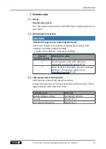
7.4.2 Assembly

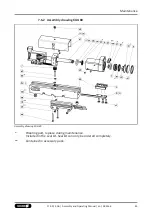
Position of the item numbers 

Assembly drawings

[

}

 42]

Assembly takes place in the opposite order to disassembly.
Observe the following:
• When pushing the gripper fingers (3,23) into the housing (1,24)

from the side with the guides (2) and the racks (8,21), you have
to make sure that both the racks (8,21) meet the pinion (7) at
the same time in order to ensure that the movement of the
gripper fingers (3,23) is synchronous.

• Where nothing else is specified, secure all bolts with Adhesives,

tighten these with a torque

Screw tightening torques

[

}

 41].

Adhesives to secure the screws

Adhesive

Item

WEICON 302-41

40, 41, 67 ,68
69 (only KGG 80, 100, 140)

Prominently equivalent adhesives can be used.

7.5 Screw tightening torques

Position of the item numbers, 

Assembly drawings

[

}

 42]

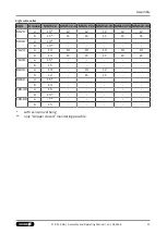
Tightening torque for screws [Nm]

Item

KGG

60

70

80

100

140

40

0.13

0.38

0.38

0.78

2.20

41

0.18

1.14

1.30

1.30

2.20

44

0.56

1.14

-

-

-

41

17.00 | KGG | Assembly and Operating Manual | en | 389166

Summary of Contents for KGG 100

Page 1: ...Translation of the original manual Assembly and Operating Manual KGG 2 Finger Parallel Gripper...

Page 2: ...n 17 00 10 06 2021 en Dear Customer thank you for trusting our products and our family owned company the leading technology supplier of robots and production machines Our team is always available to a...

Page 3: ...nal changes 8 2 4 Spare parts 9 2 5 Gripper fingers 9 2 6 Ambient conditions and operating conditions 9 2 7 Personnel qualification 10 2 8 Personal protective equipment 11 2 9 Notes on safe operation...

Page 4: ...dio system RSS R1 T2 36 6 Troubleshooting 37 6 1 Product is not moving 37 6 2 Product is not executing the complete stroke 37 6 3 Product is opening or closing abruptly 37 6 4 Gripping force is droppi...

Page 5: ...basic understanding and may differ from the actual product design In addition to these instructions the documents listed under Applicable documents 6 are applicable 1 1 1 Presentation of Warning Labe...

Page 6: ...KGG 70 KGG 80 KGG 100 KGG 140 1 1 4 Variants This operating manual applies to the following variations KGG 60 20 KGG 60 40 KGG 70 24 KGG 70 48 KGG 80 30 KGG 80 60 KGG 100 40 KGG 100 80 KGG 140 60 KGG...

Page 7: ...mperature HT 395510504 KGG 100 5520758 KGG 100 High temperature HT 5520759 KGG 140 5510565 KGG 140 High temperature HT 395510565 1 4 Accessories A wide range of accessories are available for this prod...

Page 8: ...in a machine system The applicable guidelines must be observed and complied with The product is intended for industrial and industry oriented use Appropriate use of the product includes compliance wit...

Page 9: ...ither the open or closed position in a de energized state Only change gripper fingers if no residual energy can be released Make sure that the product and the top jaws are a sufficient size for the ap...

Page 10: ...lated to the product Trained electrician Due to their technical training knowledge and experience trained electricians are able to work on electrical systems recognize and avoid possible dangers and k...

Page 11: ...ting protective clothing and also wear long hair in a hairnet when dealing with moving components 2 9 Notes on safe operation Incorrect handling of the personnel Incorrect handling and assembly may im...

Page 12: ...or in case of malfunctions Immediately remove the product from operation and report the malfunction to the responsible departments persons Order appropriately trained personnel to rectify the malfunct...

Page 13: ...njury due to unexpected movements If the power supply is switched on or residual energy remains in the system components can move unexpectedly and cause serious injuries Before starting any work on th...

Page 14: ...chnical data is included in the catalog data sheet Whichever is the latest version Ambient conditions and operating conditions Designation KGG Ambient temperature C min max 5 90 Protection class IP 40...

Page 15: ...d of application for universal use in clean environments with light to medium workpiece weights and a large stroke range Functional description The aligned base jaws are actuated with compressed air d...

Page 16: ...sible If the maximum permissible finger weight or the permissible mass moment of inertia of the fingers is exceeded the gripper can be damaged A jaw movement always has to be without jerks and bounce...

Page 17: ...ressed air lines to the main air connections A and B Screw in air connections plug connections OR Screw on throttle valve in order to be able to perform sufficient throttling and or damping 5 Screw th...

Page 18: ...Switch off the power supply and secure against restarting Make sure that no residual energy remains in the system Evenness of the mounting surface The values apply to the whole mounting surface to whi...

Page 19: ...engagement of Y mm for fastening of the gripper laterally must always be observed Connections at the housing Item Mounting KGG 60 70 80 100 140 1 Centering sleeve 5 5 6 8 8 Gripper fastening from abo...

Page 20: ...r supply and secure against restarting Make sure that no residual energy remains in the system CAUTION Damage to the gripper is possible If the maximum permissible finger weight or the permissible mas...

Page 21: ...a hose free direction connection use the O rings from the enclosed pack Air connections Thread diameter of the air connections Connection KGG 60 70 80 100 140 Hose free direct connection at the base a...

Page 22: ...re included in the scope of delivery for the sensors and are available at schunk com Information on handling sensors is available at schunk com or from SCHUNK contact persons 5 3 1 Overview of sensors...

Page 23: ...le difference in stroke based on the nominal stroke For grippers with X mm nominal stroke per jaw Min query range per jaw min queried stroke difference per jaw X 5 mm 30 of the nominal stroke per jaw...

Page 24: ...b A view of cable outlet left B view of cable outlet right A Left cable outlet KGG Setting dimension mm MMS22 A MMS P 22 MMS 22 PI1 MMS 22 PI2 MMS 22 IOL 60 20 l2 a 34 34 37 9 37 9 37 2 l2 b 21 21 24...

Page 25: ...18 19 18 18 18 l2 b 1 3 1 1 1 70 48 l2 a optimum mode only l2 b 80 30 l2 a 18 15 5 l2 b 0 0 80 60 l2 a optimum mode only l2 b 100 40 l2 a optimum mode only l2 b 100 80 l2 a optimum mode only l2 b Wit...

Page 26: ...mends cutting the sensor holder to size according to the following table Notches on sensor holder Left cable outlet KGG Groove MMS 22 MMS 22 A MMS P 22 MMS22 PI1 MMS22 PI2 MMS22 IOL 60 20 a L3 L2 L2 L...

Page 27: ...3 L2 L2 L2 L2 L2 b L1 L1 L1 L1 L1 L1 60 40 a L4 b L3 70 24 a L4 L3 L3 L3 L3 L3 b L4 L1 L1 L1 L1 L1 70 48 a L5 b L5 80 30 a L4 L3 L2 b L2 L1 L1 80 60 a L5 b L4 100 40 a L5 b L3 100 80 a b L5 with senso...

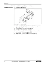
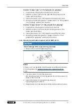
Page 28: ...r Installing the sensor with mounting kit 2 Fasten the switching lug 1 with screw 2 horizontally on the right gripper finger 3 Insert sensor 3 from below into holder 5 4 Insert the screws 4 into the h...

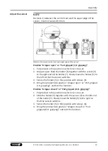
Page 29: ...he sensor switches 3 Secure the holder 5 in this position with screws 4 4 Bring the product into position Gripper open or Part gripped I D gripping and test the function Position Gripper closed or Par...

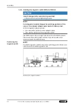
Page 30: ...le Adapter plate made of ordinary steel At ferromagnetic adapter plates First mount the product on the adapter plate Then set the position of the magnetic switch The RMS sensors have a larger hysteres...

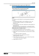
Page 31: ...ches 3 Secure the sensor 1 1 in this position using the set screw 4 Bring the product into position Gripper closed or Part gripped O D gripping and test the function 5 3 6 Mount programmable magnetic...

Page 32: ...ng torque NOTE If there is no T nut available slide the sensor according to dimension I1 into the groove 2 Setting dimensions for magnetic switches 24 1 Turn the sensor 1 into the groove 2 OR Slide th...

Page 33: ...mal position in the groove itself SCHUNK recommends Optimal Mode for setting the sensors Setting the sensor in Optimum mode 1 Put product in the position in which it is to be set 2 Hold teaching tool...

Page 34: ...the sensor according to dimension I1 into the groove 2 Setting dimensions for magnetic switches 24 1 Turn the sensor 1 1 into the groove 2 OR Slide the sensor 1 1 into the groove 2 until the sensor 1...

Page 35: ...according to dimension I1 into the groove 2 Setting dimensions for magnetic switches 24 1 Turn the sensor 1 into the groove 2 OR Slide the sensor 1 into the groove 2 until the sensor 1 stops at the T...

Page 36: ...2 OR Slide the sensor 1 into the groove 2 until the sensor 1 stops at the T nut 3 2 Mount the sensor 1 using the set screw Tightening torque 10 Ncm 3 Adjust sensor 1 see Translation of Sensor Assembl...

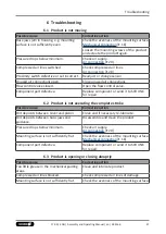
Page 37: ...end it to SCHUNK for repair 6 2 Product is not executing the complete stroke Possible cause Corrective action Dirt deposits between cover and piston Clean and if necessary re lubricate Dirt deposits b...

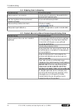
Page 38: ...alled optimally If present Open the flow control couplings on the product to the maximum that the movement of the jaws occurs without bouncing and hitting Check compressed air lines Inner diameters of...

Page 39: ...cycles Maintenance work 2 Treat all grease areas with lubricant Lubricants Lubrication points 39 2 Clean all parts thoroughly check for damage and wear if necessary replace seals Assembly drawings 42...

Page 40: ...ers 3 and 23 5 Remove the O rings 26 from the covers 6 6 KGG 60 70 Unscrew the countersunk screws 44 KGG 80 100 140 Remove the hexagon nuts 63 7 Remove the pistons 5 from the gripper fingers 3 and 23...

Page 41: ...ngers 3 23 into the housing 1 24 from the side with the guides 2 and the racks 8 21 you have to make sure that both the racks 8 21 meet the pinion 7 at the same time in order to ensure that the moveme...

Page 42: ...s They serve for illustration and assignment of the spare parts Variations are possible depending on size and variant 7 6 1 Assembly drawing KGG 60 and KGG 70 Assembly drawing KGG 60 and KGG 70 Wearin...

Page 43: ...drawing KGG 80 Assembly drawing KGG 80 Wearing part replace during maintenance Included in the seal kit Seal kit can only be ordered completely Contained in accessory pack 43 17 00 KGG Assembly and O...

Page 44: ...perating Manual en 389166 7 6 3 Assembly drawing KGG 100 and KGG 140 Assembly drawing KGG 100 and KGG 140 Wearing part replace during maintenance Included in the seal kit Seal kit can only be ordered...

Page 45: ...303050 0340311 The partly completed machine may not be put into operation until conformity of the machine into which the partly completed machine is to be installed with the provisions of the Machiner...

Page 46: ...overall machine Fulfilled for the scope of the partly completed machine Not relevant 1 1 Essential Requirements 1 1 1 Definitions X 1 1 2 Principles of safety integration X 1 1 3 Materials and product...

Page 47: ...stics of guards and protective devices 1 4 1 General requirements X 1 4 2 Special requirements for guards X 1 4 2 1 Fixed guards X 1 4 2 2 Interlocking movable guards X 1 4 2 3 Adjustable guards restr...

Page 48: ...n from Annex 1 is to be supplemented from here forward 2 Supplementary essential health and safety requirements for certain categories of machinery X 2 1 Foodstuffs machinery and machinery for cosmeti...

Page 49: ......

Page 50: ......

Page 51: ......

Page 52: ...Clamping and gripping technology Bahnhofstr 106 134 D 74348 Lauffen Neckar Tel 49 7133 103 0 Fax 49 7133 103 2399 info de schunk com schunk com Folgen Sie uns I Follow us 06 2021 2021 SCHUNK GmbH Co...

Reviews: