background image

 
 Assembly and Operating Manual 
 
AGE-F-XY 

– Compensation Unit with spring return 


10 

Date printed 28.12.2009 

Maintenance and care 

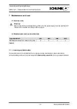
7.1  Service note 


Warning! 

Before assembling or disassembling of the unit, the power supply must be switched off.


 Please also consider the safety hints on page 4. 


7.2  Maintenance and service intervals 


Type AGE-E-XY 

031 

040 

062 

080 

Maintenance interval in millions of cycles 

Table 6 


7.1  Cleaning and lubrication 

Some parts have to be installed with oil or grease during maintenance (basic lubrication). 
All metal sliding surfaces must be treated with 

Rexroth Dynalub 510

 or an equivalent lubricant.  


Summary of Contents for AGE-F-XY

Page 1: ...mplete satisfaction SCHUNK products are inspiring Our detailed assembly and operation manual will support you Do you have further questions You may contact us at any time even after purchase You can r...

Page 2: ...MPLE OF AN ASSEMBLY 6 5 2 MOUNTING THE MODULE TO THE MANIPULATOR 7 5 3 SETTING THE BACK STOP TO LIMIT STROKE 8 6 TROUBLESHOOTING 9 7 MAINTENANCE AND CARE 10 7 1 SERVICE NOTE 10 7 2 MAINTENANCE AND SER...

Page 3: ...may be used only within the range of its technical data Any other use is deemed improper and unintended use The manufacturer will not be liable for any damages resulting from improper use 1 3 Environ...

Page 4: ...wer supply cables must be removed for assembly modification maintenance and adjustment of the unit 8 Carry out all maintenance modifications or attachments outside of the danger zone 10 During install...

Page 5: ...ontact with the workpiece and wearing parts are not covered by the war ranty See also our General Terms and Conditions in this regard 3 Scope of delivery The scope of delivery includes Compensation un...

Page 6: ...ing to DIN 9409 to be provided optionally by SCHUNK or the customer 3 Mounting screws for adapter plate 4 Compensation unit AGE F XY 5 Handling device e g gripper Table 2 Designation of components An...

Page 7: ...Using two cylindrical pins fix the module over the fixing bores 2 Use an Allen key to tighten the mounting screws item 31 Type AGE E XY 031 040 063 080 Thread diameter and max depth of engagement Y to...

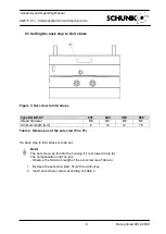
Page 8: ...080 thread diameter M3 M3 M4 M4 minimum length mm 6 12 12 18 Table 4 Dimensions of the set screw Pos 51 If a back stop to limit stroke is to be set Note The set screw can fall into the housing if it i...

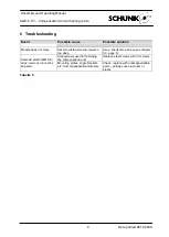
Page 9: ...Set screw stop screw screwed in too deep Use a shorter stop screw see chapter 5 3 page 8 Solenoid switch MMS P does not work cannot be adjusted Steel screws used for fastening the compensation unit Re...

Page 10: ...ply must be switched off Please also consider the safety hints on page 4 7 2 Maintenance and service intervals Type AGE E XY 031 040 062 080 Maintenance interval in millions of cycles 2 2 2 2 Table 6...

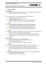
Page 11: ...the upper part of the housing item 2 Note The outer guide rails and the respective roller cages of the linear guide item 20 fall off after the upper part of the housing item 2 has been lifted 8 Lift...

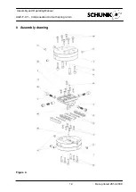
Page 12: ...Assembly and Operating Manual AGE F XY Compensation Unit with spring return 12 Date printed 28 12 2009 8 Assembly drawing Figure 4...

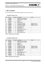
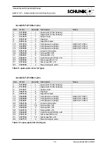
Page 13: ...1 9660081 4 Screws M2 5 x 10 40 9950193 6 Cylindrical pin 1 0m6 x 6 50 9907233 4 Set screw M5 x 6 51 9670002 8 Set screw M3 x 4 60 9941633 2 Round magnet axial Table 7 spare parts list of all types 9...

Page 14: ...14 50 9900560 4 Set screw M12 x 10 51 9670042 8 Set screw M4 x 10 60 9948909 2 Round magnet axial Table 9 spare parts list of all types 9 4 AGE F XY 080 1 2 3 Item ID No Quantity Description Notes 1 5...

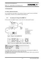
Page 15: ...nd in the data sheets for sensors Figure 5 Magnetic switch MMS P 22 Figure 6 Connection diagramm PNP 4 conductor MMS P 22 Type ID No MMS P 22 S M8 PNP 0301370 MMSK P 22 S PNP 0301371 V2 M8 4 2XM8 3 03...

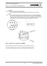
Page 16: ...tic material e g standard construction steel are used the gripper must first be mounted on the adapter plate before set ting the positions of the magnetic switches This is necessary because the use of...

Page 17: ...ity to trouble and dam age increases In the mode of the lowest hysteresis an error signal such as jitter or untimely switch off can be avoided if the sensor is protected against all types of distur ba...

Page 18: ...strict Shanghai 200032 Tel 86 21 64433177 Fax 86 21 64431922 info cn schunk com www cn schunk com FRANCE SCHUNK Intec SARL Parc d Activit s des Trois Noyers 15 Avenue James de Rothschild Ferri res en...

Page 19: ...223 7665 info mx schunk com www mx schunk com PORTUGAL Sales Representative Victor Marques Tel 34 937 556 020 Fax 34 937 908 692 Mobil 351 963 786 445 info pt schunk com www pt schunk com SPAIN SCHUNK...

Reviews: