Assembly
32
01.00|1416054_ROTA-M2 + 2 |en
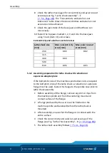
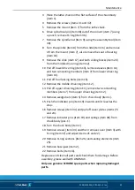
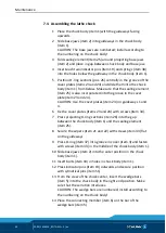
8 Check the lathe chuck again for concentricity and axial run-out
accuracy (see Fig. "Lathe chuck assembly" - E
). The "Concentricity and axial run-out
tolerances" table shows the concentricities and axial run-out
accuracies to be achieved.
9 Check the jaw stroke of the base jaws and that these can
move easily.
10 Fasten the top jaws marked 1, 2, 3 and 4 to the base jaws
using T-nuts (item 41) and screws.
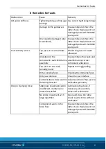
Concentricity and axial run-out tolerances
Lathe chuck size
[mm]
Max. concentricity
error [mm]
Max. axial run-out
error [mm]
260
0.03
0.02
315
400
0.04
500
630
0.06
0.03
Assembly preparation for lathe chuck with reduction or
expansion adapter plate
If the bolt pitch circle of the machine spindle does not correspond
to the bolt pitch circle of the lathe chuck, a reduction or extension
flange must be used. Fasten this flange to the spindle nose prior to
lathe chuck assembly.
1 Before assembly of the flange, remove any dirt or chips from
the machine spindle and from the centering mount and
contact surface of the flange.
2 A flange produced by the user must be finished on the
machine spindle and balanced before the lathe chuck is
mounted.
3 After assembly, ensure that the flange is in contact with the
entire surface.
4 Check the concentricity and axial run-out accuracy of the
flange (see Fig. "Lathe chuck assembly" - B
).
5 The lathe chuck assembly follows
5.3.2


