SCHUNK 1322939 Installation And Operating Instruction Download Page 5


_________________________________________________________________________________________ 

schunk.com 


XND.00033.002_B – 05/2022   


 22


2.2


Reasonably foreseeable misapplication 

Any application that is not in accordance with the "Intended use" or exceeds such  
intended use is considered not in accordance with the regulations, and is forbidden. 
Any other use of the device is subject to confirmation from the manufacturer. 

Examples of forseeable misapplication 


Clamping device used on rotating systems. 


Clamping widely protruding workpieces. 


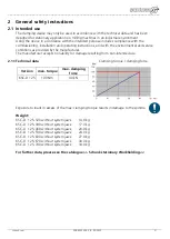
Clamping workpieces with a weight of over 20 kg in vertical position without an additional 
safeguard to prevent the workpiece falling out. 

2.2.1


Alterations and modifications 

In the case of unauthorised alterations and modifications of the clamping device,  
the manufacturer's liability ceases and any warranty is voided. 

2.2.2


Spare and wear parts and auxiliary material 

Only use original parts or parts approved by the manufacturer. Using spare and wear parts by 
third party manufacturers may lead to risk. 

2.3


Residual risk 

The user is responsible for applying the correct workpiece tension. 
New clampings have to be carefully checked by qualified personnel with relevant training.  
One always needs to allow for the risk that the workpiece may slip or be dislodged, even 
when the clamping device is functioning correctly. This is due to the different geometries to 
be clamped, contact surfaces, clamping friction values, processing force, wrong manipulation 
of the milling machine etc.  
Protective devices are to be attached to the processing machine that will protect the operator 
from any tool or workpiece parts that may be ejected. 
It is mandatory that operators and others in the proximity of the processing machine wear 
protective goggles. 
Do not use methods of operation that impair the function and operational safety. 

2.3.1


Jaw change


Damage may result if system jaws are insufficiently tightened. 

2.3.2


Notes on clamping technology 

The operator is responsible for ensuring that the clamping geometry and clamping forces  
are suitable for the intended processing.  
We recommend that clamping be carried out with a torque wrench in order to achieve 
consistent clamping results. 
The clamping forces can only be achieved if the clamping device functions correctly  
and the workpiece is correctly held in the device. 
Regular servicing and cleaning in accordance with the operating instructions is  
mandatory in order to ensure correct function.  
When clamping thin-walled elastic workpieces, e.g. tubes or packages, it is possible  
that the clamping force is significantly reduced due to yielding of the workpiece. 
When clamping with a high degree of force, the clamping force is significantly reduced  
due to the increased frictional forces in the carriages. 

Summary of Contents for 1322939

Page 1: ..._____________________________________ schunk com XND 00033 002_B 05 2022 1 Montage und Betriebsanleitung Installation and operating instruction Doppelspanner Double vice KSC D 125 H D SCHUNK GmbH Co S...

Page 2: ...qualification 23 2 7 Personal protective equipment 23 2 8 Warranty 23 3 Description of the clamping device 24 3 1 Application 24 3 1 1 Adjusting jaws 24 3 1 2 Setting up the third hand function 25 3...

Page 3: ...ates a potentially dangerous situation If the information is ignored it is possible that death or serious injury permanent disability will result WARNING Indicates a potentially dangerous situation If...

Page 4: ...al and service conditions as provided by the manufacturer The manufacturer accepts no liability for damage resulting from non intended use 2 1 1Technical data Exposure to loads in excess of the max cl...

Page 5: ...slodged even when the clamping device is functioning correctly This is due to the different geometries to be clamped contact surfaces clamping friction values processing force wrong manipulation of th...

Page 6: ...hine and to observe these instructions 2 6 Operator qualification The installation initial setup fault analysis and periodic monitoring have to be carried out by competent personnel with the relevant...

Page 7: ...ed air The third hand operation function when clamping is guaranteed by pre clamping the rear carriage using a pressure spring 3 1 Application 3 1 1Adjusting jaws For two identically sized or differen...

Page 8: ...he workpiece first where it pre tensions to around 500 N After the front jaw A comes into contact with the workpiece the rear clamping jaw B starts to close Once both workpieces have been clamped the...

Page 9: ...aws Attachment thread M4 in the base body for alignment using alignment and centring sets Threads M12 at the front on reference surface The KSC D can also be produced at the factory with customer spec...

Page 10: ...recommend cleaning the double vice when replacing jaws as these components are fast and easy to remove Regularly clean the vice through the two cleaning holes on the face of the front carriage using...

Page 11: ...iage unit from the base body Unscrew the clamping screw pos 230 Remove the central jaw and blow out the body through the blow out holes on the front carriager pos 70 Important Vice functions can exclu...

Page 12: ...e unit is now positioned around 20 mm over the centre Important Carriage unit must not come into contact with the rear cylinder screw pos 160 Fully tighten the clamping screw pos 230 and undo by turn...

Page 13: ..._________________________________________________________________________________________ schunk com XND 00033 002_B 05 2022 30 9 Assembly drawing...

Page 14: ...ge L 390 rear carriage L 460 rear carriage L 530 rear carriage L 600 rear carriage L 670 rear carriage L 740 rear carriage 1 70 DGM 125 505 81 DGM 125 515 81 DGM 125 525 81 DGM 125 535 81 DGM 125 545...

Page 15: ...ded pin SP M10x20 1 270 DGZ 125 063 11 Position bar 2 280 XNN 10311 463 Internal hexagon cylinder screw M10x20 12 9 4 Note Pos 10 60 and 70 cannot be supplied as individual spare parts as these are de...

Page 16: ...nto account that during the first clamping process the 6 fold reversible jaws can yield slightly until the play in the peg seating is eliminated The workpiece position must be measured the zero point...

Page 17: ...p the workpiece so that the clamping faces are parallel to the workpiece Use a torque of 80 Nm to tighten the cylinder screws of the 6 fold reversible jaws Important When the clamping faces of the 6 f...

Page 18: ...rea of the disassembled middle jaw is not included in the standard scope of delivery of the double vise The disassembly to the double clamp is done in reverse order 13 Positioning bar For the lengths...

Page 19: ...______________________________________________________ schunk com XND 00033 002_B 05 2022 36 H D Schunk GmbH Co Spanntechnik KG Lothringer Strasse 23 D 88512 Mengen Tel 49 7572 7614 0 Fax 49 7572 7614...

Reviews: