background image

23

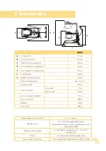
5. Technical data.

tram.

A

Total width

70 cm

B

max. total width

102 cm

C

Width of torso guidance

56 cm

D

min. height torso guidance

110 cm

E

max. height torso guidance

147 cm

F

Total length

116 cm

G

Height to push handle

110 cm

Body circumference

56 - 152 cm

Turning radius

127 cm

Chassis height

low model

11 cm

high model

17.5 cm

min. arm support height

77 cm

max. body size

193 cm

Weight

32 kg

max. load

158 kg

E

F

G

D

A

B

C

Stroke speed (without load)

4 cm / second

Battery pack

12V - 2.9 Ah led gel battery pack

(replacement battery packs available from your 

specialist dealer)

Battery pack charger

for installation at the wall, 100 - 240 V AC, 

max 650 mA

Drive

24 V, 6A, permanent magnet drive

Duty cycle of the drive

2 min. permanent use followed by 18 min. idle

Summary of Contents for rifton tram

Page 1: ...Instructions for use tram The transfer and mobility aid from Rifton tram ...

Page 2: ...s for use carefully prior to initial commissioning of the product and to observe them Please note that gui delines and representations in these Instructions for use may deviate from your product due to differing equipment We reserve the right to make technical modifications Important information Ensure that these Instructions for use remain with the product Your schuchmann Team ...

Page 3: ...s 09 2 7 Product overview 09 3 Settings 10 3 1 Push handle 10 3 2 Battery pack box 11 3 3 Battery pack display 11 3 4 Emergency off button 12 3 5 Emergency lowering button 12 3 6 Scales optional 12 3 7 Direction locks optional 14 3 8 Leg expander 14 3 9 Body support system 15 3 10 Padded forearm supports optional 15 3 11 Leg straps for seated transfer 17 3 12 Groin harness optional for standing up...

Page 4: ...5 8 1 Assembly of the charger 25 8 2 Charging the battery pack 25 9 Identification 26 9 1 EU Declaration of Conformity 26 9 2 Serial number date of manufacture 27 9 3 Product version 27 9 4 Issue of the document 27 9 5 Name and address of the manufacturer specialist dealer supplying the product 27 ...

Page 5: ...ey included in the delivery and first remove the 4 screws on the adapter A Then please hold the push handle on the ad apter B and fasten the screws first at the top with the Allen key Finally remove the cover on the front side of the battery pack box insert the connector of the push handle into the intended adapter C and mount the cover once again 1 2 Safety measures prior to use The correct use o...

Page 6: ...eproduct according to their nature see material information under point 2 1 1 4 Where to store the Instructions for use Please store these Instructions for use carefully and ensure that these Inst ructions for use remain with the product in case of re use Should you lose the instructions you can always download an updated version at www schuchmann de 1 Preparation 2 Product description 2 1 Materia...

Page 7: ...physical conditions 2 3 1 Indication The tram transfer and mobility aid is designed for users who manifest a significant to fully pronounced impairment of being able to change body position and walking This is often the result neuromuscular damage am putation of one of the lower extremities of the lower extremities or with neurological disorders 2 3 2 Contraindications In general the indications f...

Page 8: ...teral stabilisation The strap system must be carefully adjusted in order to guarantee the safety of the patient Ensure prior to each use of the transfer and mobility aid that the straps are safely hooked into the coloured clips Never leave a patient unattended in the transfer and mobility aid Observe the max load and the max body height see Point 5 Do not use the transfer and mobility aid if it ha...

Page 9: ...2 6 List of accessories Padded forearm supports Groin harness Additional leg straps Direction locks 2 7 Product overview The Fig below is intended to show you the designation of the most important components as well as the terms which you will find in these Instructions for use Body support system Scales rear dual castors front dual castors incl direction lock Base frame Leg straps Leg expander Di...

Page 10: ... respective area when making adjustments of any kind to minimise the risk of injury 3 1 Push handle The push handle permits the accom panying person to manoeuvre the tram It is removed for shipping and must be installed first see Point 1 1 With the aid of the integrated ope rating switch A the accompanying person can lift or lower the body support system with only one single switch which is positi...

Page 11: ...low charge battery pack soon red low charging status An acoustic signal sounds when the battery pack is completely empty Up to 70 lifting procedures can be carried out with a fully charged battery pack In order to avoid damage to the battery pack charge this as soon as the yellow lamp lights up The control lamp goes out after approx 10 minutes after the last activation of the operating switch on t...

Page 12: ...ack is in the red range Every accompanying person must familiarise themselves with the position and operation of the emergency stop button and the emergency lowering button 3 6 Scales optional The optional scales of the tram permit the accompanying person easy weighing of a patient during a routine transfer In addi tion the operator can determine possible strains but also advancements of a patient...

Page 13: ...using the groin har ness see Point 3 12 The load which can be taken over by patients can now be read off the display please ignore the minus sign To change the batteries press on the outsi de of the cover B remove it and insert new batteries AA For exact determination of the weight the patients must be completely lifted up The feet or legs may not contact the floor or the base frame of the tram Ge...

Page 14: ...y has been inserted correctly Use To use a direction lock the respective castor must be aligned so that it is straight B Then press the pin A downwards as far as it will go Pull the pin back up again in order to deactivate the direction lock 3 8 Leg expander Thanks to its compact size the tram fits without any problems through a 76 cm narrow door frame Lifting into or out of wide wheelchairs is gu...

Page 15: ...0 Paddedforearmsupports optional The padded forearm supports of the tram offer patients with limited muscle tone or the arms of which must be secured additional support when standing and walking In order to fulfil all requirements they permit align ment in any direction If the padded forearm supports are ordered to gether with the tram the brackets are already pre mounted Mounting the brackets If ...

Page 16: ...en the screw connection C For different lower arm lengths the handle D can now be pushed forwards or backwards The angle too can be brought into the correct position The arm strap E and the hand loop F secu re the arm on the lower arm support In ad dition the hand loop F prevents inadvertent slipping from the underarm support After installation please re tighten all screw connections Removal of th...

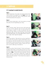
Page 17: ...he strap tight and ensure that both leg straps are positioned below the pati ent s thighs and adjusted equally Step 4 Lift up the patient Observe the process carefully to ensure that the patient is sitting comfortable and is not sagging Now the transfer can be carried out If necessary activate the direction locks to make pus hing in a straight direction easier Loosen the direc tion locks for sidew...

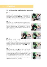
Page 18: ...to the rear side of the body support system as shown in the two photos on the right Step 3 If you lift the patient pull the tram gently towards yourself to imitate the natural curved process of standing up Monitor the process precisely to ensure that the patient is supported appropriately and comfortably by the tram while being lifted Step 4 Adjust the height of the tram in such a way that the pat...

Page 19: ...m Step 2 Loosen and remove the leg straps one after the other so that the patient s feet touch the ground and can bear some weight The padded torso guidance and the arms of the patient bear the rest of the weight Step 3 Take off the required clothing so that the patient can go to the toilet Step 4 Lower the patient onto the toilet seat tram permits the patient to use the to ilet privately while be...

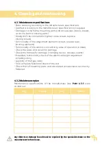
Page 20: ...d evenly applied with a soft cloth Alternatively wipes pre soaked with disinfectant can be used to wipe the products over the entire surface In both cases care must be taken to ensure complete wetting Disinfection in fully automatic disinfection systems is also possible and recommended The exposure times may vary and can be found in the manufacturer s ins tructions for the products used 4 2 Servic...

Page 21: ...castors concentricity ease of operation brakes Check the pads and covers for damage Check the harness for damage clamping device closures seams If needed functionality check of the electrical height adjustment including wiring Legibility of the type label Final complete functional check of the aid Check that all mounting parts and associated accessories are correctly fastened 4 3 2 Maintenance pla...

Page 22: ...over and above this time period if it is in a safe condition The expected duration of use does not refer to wear parts such as for example wheels gas pressure springs The maintenance and evaluation of the condition and if applicable the potential for re use must be decided by the specialist dealer The product is suited for re use Prior to forwarding please follow the clea ning and disinfection ins...

Page 23: ...7 cm Chassis height low model 11 cm high model 17 5 cm min arm support height 77 cm max body size 193 cm Weight 32 kg max load 158 kg E F G D A B C Stroke speed without load 4 cm second Battery pack 12V 2 9 Ah led gel battery pack replacement battery packs available from your specialist dealer Battery pack charger for installation at the wall 100 240 V AC max 650 mA Drive 24 V 6A permanent magnet ...

Page 24: ... be applied is perceived The telescopic lifting column is then immediately lif ted a little If for example the body support system is pressed onto the hips or upper thighs a clear beep will sound and the drive will be stopped This beep will only cease after the operating switch is released This system is highly sensitive and may occasionally emit a false alarm This is in parti cular the case if th...

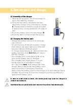
Page 25: ...ven if the bat tery pack display still shows green To charge the battery pack remove it from the battery pack box see Point 3 2 and insert it into the charger The charging and control lamp lights up as soon as the battery pack is charged The charging time totals approx 6 hours During a period of prolonged storage non use of the tram the battery pack loses charge Please ensure that the battery pack...

Page 26: ...ührten Richtlinien und Standards entspricht is are in conformity with the requirements of the below listed directives and standards Verordnung EU 2017 745 über Medizinprodukte vom 05 April 2017 Regulation EU 2017 745 on medical devices of 5 April 2017 DIN EN 12182 2012 Technische Hilfen für behinderte Menschen Technical aids for disabled persons DIN EN ISO 14971 2013 Medizinprodukte Anwendung des ...

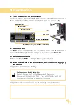
Page 27: ...9 2020 9 5 Name and address of the manufacturer specialist dealer supplying the product This product was manufactured by This product has been delivered by the following specialist dealer Schuchmann GmbH Co KG Rudolf Runge Str 3 49143 Bissendorf Germany Phone 49 0 5402 40 71 00 Fax 49 0 5402 40 71 109 info schuchmann de www schuchmann de A Product name Item number Serial number schuchmann de info ...

Page 28: ...schuchmann de GA 47 EN_1 0 ...

Reviews: