background image

VME64x System Subrack 2 U

20836-245

www.schroff.biz

I

R1.0, July 14, 2009

Table of Contents

1

Safety ................................................................................................................. 1

1.1

Intended Application ............................................................................................  1

1.2

Safety Instructions ...............................................................................................  2

1.2.1

Safety Symbols used in this document ..................................................  2

1.3

General Safety Precautions.................................................................................  2

1.4

References and Architecture Specifications ........................................................  3

2

Product Definition............................................................................................. 4

2.1

Subrack System Overview...................................................................................  4

2.2

VME64x Backplane .............................................................................................  5

2.3

Power Backplane.................................................................................................  5

2.4

Power Supply.......................................................................................................  6

2.4.1

Grounding/Earthing................................................................................  6

2.4.2

Plug-In AC Power Supply (Order separately) ........................................  7

2.4.3

Wiring Diagram ......................................................................................  8

2.5

Cooling.................................................................................................................  9

3

Assembly......................................................................................................... 10

3.1

General Assembly Guidelines ...........................................................................  10

3.1.1

Unpacking ............................................................................................  10

3.1.2

Ensuring Proper Airflow .......................................................................  10

3.2

Rack-Mounting...................................................................................................  11

4

Service ............................................................................................................. 12

4.1

Technical support and Return for Service Assistance .......................................  12

4.2

Declaration of Conformity ..................................................................................  12

4.3

Delivery comprises ............................................................................................  13

4.4

Accessories .......................................................................................................  13

4.5

Replacement Parts ............................................................................................  13

5

Technical Data ................................................................................................ 14

6

Dimensions ..................................................................................................... 15

Summary of Contents for VME64x

Page 1: ...VME64x System Subrack 2 U User s Manual Product No 20836 245 July 14 2009 Doc No 63972245_R1 0...

Page 2: ...Management System to EN ISO 9001 2000 The company cannot accept any liability for errors or misprints The company reserves the right to amendments of technical specifications due to further developme...

Page 3: ...Overview 4 2 2 VME64x Backplane 5 2 3 Power Backplane 5 2 4 Power Supply 6 2 4 1 Grounding Earthing 6 2 4 2 Plug In AC Power Supply Order separately 7 2 4 3 Wiring Diagram 8 2 5 Cooling 9 3 Assembly...

Page 4: ...VME64x System Subrack 2 U 20836 245 www schroff biz II R1 0 July 14 2009...

Page 5: ...s no valid approval for these units In order to enable stand alone functionality additional elements are required An operational system is achieved only by way of appropriate VME64x boards The complet...

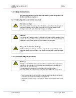
Page 6: ...ns to avoid accidents before starting to work with parts that carry dangerous voltages Caution This is the user caution symbol It indicates a condition where damage of the equipment or injury of the s...

Page 7: ...anual VME64x J1 J2 Monolithic Backplanes Order no 73972 128 Short Form User Manual Power Backplane 23098 115 Order no 73972 072 Operating Instructions maxpowerPRO 250 W Power Supply 13100 141 Order no...

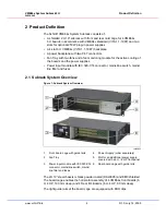
Page 8: ...supplies Power input module with IEC 320 C14 connector mains line switch mains line filter and fuses 2 1 Subrack System Overview Figure 1 Subrack System Overview The 2 U 19 steel chassis is black pow...

Page 9: ...nector for the Fan Tray Further information can be found in the user manual of the backplane Order No 73972 103 in the catalogue or on the internet at www schroff biz 2 3 Power Backplane A Power Backp...

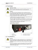
Page 10: ...ieved through the protective earth conductor of the power cable Hazardous voltage Parts of the power supply may be exposed with hazardous voltage Always remove mains line connector before carry out an...

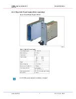
Page 11: ...upply e 10006814 Input voltage nominal 100 240 VAC Mains Frequency 50 60 Hz Output max 250 W Output voltages 3 3 5 0 12 0 12 0 V V V V 40 40 5 5 2 A A A A Ripple 1 Dynamic response 1 or 60 mV Recovery...

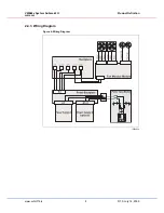
Page 12: ...VME64x System Subrack 2 U Product Definition 20836 245 www schroff biz 8 R1 0 July 14 2009 2 4 3 Wiring Diagram Figure 4 Wiring Diagram 10009834...

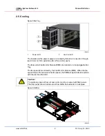
Page 13: ...Fan Monitor Module FMM are located on a hot pluggable Fan Tray The fan speed is monitored by the Fan Monitor Module FMM When the fan speed drops 20 below nominal fan speed the FMM will signal a fault...

Page 14: ...ck whenever possible If installation in an enclosed rack is unavoidable ensure that the rack has adequate ventilation Maintain ambient airflow to ensure normal operation If the airflow is blocked or r...

Page 15: ...asks have to be carried out Ensure that the system has not been damaged during transport storage or assembly Carry out a new test for the protective earth set value 0 1 Ohm Switch on the system and ch...

Page 16: ...ives it is not classified as equipment therefore a CE certification is not required The systems do however fulfil all requirements in a full assembled state to the standard of EMC guideline 89 336 EWG...

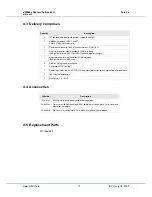
Page 17: ...de rails inc ESD clips ESD clip assembled at the right 1 Rear card cage for max 4 boards 6 U 80 mm deep IEEE guide rails inc ESD clips 2 Slots for 2 plug in power supplies 1 Complete AC DC cabling 1 P...

Page 18: ...put up to 500 W Cooling 2 x 12 VDC fans 69 m h 40 cfm each free blow Ambient Temperature Operation 0 C to 50 C Storage 40 C to 85 C Humidity Admissible humidity 30 to 80 non condensing EMC fulfils req...

Page 19: ...VME64x System Subrack 2 U Dimensions 20836 245 www schroff biz 15 R1 0 July 14 2009 6 Dimensions Figure 7 Dimensions...

Page 20: ...VME64x System Subrack 2 U Dimensions 20836 245 www schroff biz 16 R1 0 July 14 2009...

Page 21: ......

Page 22: ...SCHROFF GMBH www schroff biz Langenalberstr 96 100 Tel 49 0 7082 794 0 Fax 49 0 7082 794 200 D 75334 Straubenhardt...

Reviews: