Installation
The Load Genie has 1/2 NPT “IN” and “OUT” ports and is suit-
able for compressor with discharge capacities of up to 32
SCFM . The Load Genie is typically installed onto the tank
with a short pipe nipple. The “OUT” port must be connected
directly to the tank with no other check valves in between
the tank and the Load Genie. (NOTE: On some retrofit appli-
cations, there may have been a type of check valve known
as an “In Tank” check valve previously installed. Make sure
there is a clear air path between the tanks and “OUT” port
before installing the Load Genie. The compressor discharge
line can now be routed into the “IN” port of the Load Genie.
The installation is now complete.
Regulator Adjustment
Cutout pressure is adjustable from 60 PSI to 175 PSI with
the standard silver spring. The differential (difference
between cut-out and cut-in pressures) is typically set at the
factory at approximatly 15% of the cut-out pressure. This is
usually a suitable differential and will not normally need to
be readjusted.
1. Loosen range screw jam nut first.
2. Turn range screw clockwise to raise cut-out and cut-in
pressure levels and counter clockwise to decrease cut-
out and cut-in levels.
3. Start compressor and note cut-out and cut-in presures.
Make adjustments as necessary using range
adjustment screw; when acceptable, tighten range
adjustment screw jam nut.
4. Adjust the cut-in pressure to the desired level per
steps #1, #2, and #3, as shown above.
5. Loosen differential screw jam nut and turn differential
screw clockwise to raise cut-out pressure and
counter clockwise to decrease the the cut-out
pressure.Tighten differential screw jam nut when
desired cut-out pressure is set. Since step #5 should
not change the desired cut-in pressure set in step #4,
adjustment is now complete.
Use with Gasoline Engine
Throttle Controls
A 1/8 NPT tapped port in the end of the Load Genie allows
the use of a throttle control to slow down the driving engine
when in the cutout (venting) mode. The throttle control is
simply a small (e.g., 1/2” dia. X 1” stroke) single-acting, spring
return air cylinder which moves the throttle lever on the
engine to the idle position when the cylinder is pressurized
while in the cut-out mode. 709 Throttle control is specifi-
cally designed for this application.
It is improtant that the
throttle control air cylinder is leak-tight and that all con-
nections between that Load Genie and the air cylinder are
leak-tight.
Load Genie Instructions
9
VENT
Inlet (Connected to Compressor)
1/8 NPT
Throttle Control Port
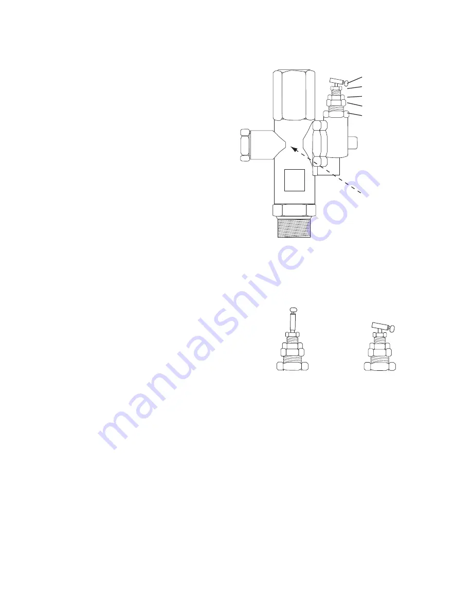
Differential Jam Nut
Differential Adjustment Screw
Range Jam Nut
Range Adjustment Screw
Out (Connected to Tank)
Vent Port
(See rear, open to
Atmosphere)
Loadgenie3 112807.ai
Easy Start Lever
Start Position
Run Position
Starting Unit
Easy Start: Place Easy Start Lever in upright position. Start unit.
When running smoothly, flip lever to run position.


