GB
17
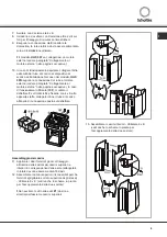
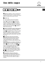
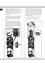
14.
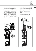
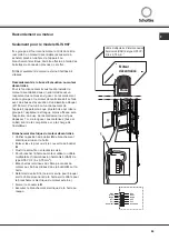
Insert the upper flue into the lower flue as far as it
can go. Block the flues together temporarily with
two screws (through the
Z2
seat).
!
These screws stop the lower flue from slipping
accidentally during the fixing operations.
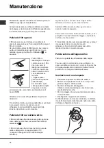
15.
Insert the upper and lower flue ensemble into the
structure (the grate cleaners must correspond to
the right and left side of the lattice).
16.
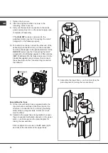
Fix above with 4 screws (2 per side).
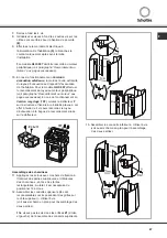
17.
If they are not already in position, partially tighten
the 4 screws on the base of the lattice; the heads
of the screws will serve as attachments for the
hood.
18.
Attach the lattice to the hood and check that the
attachment is safe. Fix the hood to the structure
with 2 screws that will also serve to centre the two
parts. Tighten the 4 attachment screws well.
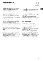
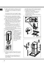
19.
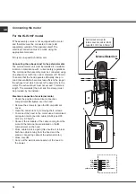
Carry out electrical connection of control panel
and bulbs.
20.
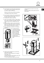
Remove the two
screws that temporarily
block the flues together
(also see installation
phase 14 and -
Z2
).
Slide the lower hood
down to completely
cover the motor until it is
inserted into the
apposite seat over the
hood.
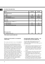
21.
Apply the 2 tabs (supplied) to cover the fixing
points of the bottom flue.
Caution! The bottom flue tabs are the narrower
and shallower ones.
The wider and deeper tabs are those used for the
top flue, and must be cut to size.
• Turn the mains power on again at the central
electrical panel and check for correct hood
operation.
• Mount the fat filters and the perimeter suction
panels again.
Ø3x9
Summary of Contents for HLI 997
Page 69: ......
Page 70: ...LI2R9E Ed 02 08 ...

