


Note:
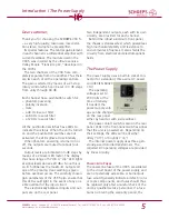
During production, the reference level of the
0 dB LED is set to +6 dBu.
”Clip” Indicator
The red ”Clip” LED has a fixed reference
voltage. It begins to blink at levels above ca.
+20 dBu, thus giving a warning before there
is any possible overload.
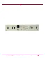
Outputs
The
SCHOEPS
VSR 5 is equipped with two
separate electronically balanced XLR outputs
per channel.
The gold-plated XLR output sockets are on
the rear panel of the unit. In accordance
with international standards, the layout is:
Pin 1 = Ground
Pin 2 = (+) Phase
Pin 3 = (–) Phase
Note: The VSR 5 has floating, servo-balanced
outputs. Thus if either pin 2 or 3 is grounded,
the output levels will remain the same as in
balanced operation.
Operating Controls
8
SCHOEPS
GmbH · Spitalstr. 20 · D-76227 Karlsruhe (Durlach) · Tel: +49 (0)721 943 20-0 · Fax: +49 (0)721 495 750
www.schoeps.de · [email protected]
button a second time. The filter selection is
stored when the preamplifier is turned off,
and is set automatically the next time the unit
is turned on.
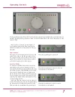
Level Indicator
The signal level indicator of the VSR 5 con-
sists of 21 LEDs including a ”Clip” LED.
The level is indicated in steps of 3 dB. The
range from -48 to -15 dB is shown in green,
the range from -12 to -3 dB in yellow, and
the LEDs for 0 to +9 dB are red, as is the
”Clip” LED.
A full-wave DIN PPM peak detector drives
the display with an attack time of <10 ms
and a decay time of 0.5 seconds per 20 dB.
Here the 80-Hz low-cut filter has been acti-
vated.
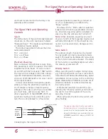
Do not connect the plug connector's
housing to pin 1.
Do not connect the plug connector's
housing to pin 1.
In this case pin 3 must be connected
to pin 1 (ground), since pins 2 and 3 of
the output from the VSR 5 are floating.
VSR 5 output socket
VSR 5 output socket
balanced
input
unbalanced
input
Connecting the inputs and outputs of the VSR 5
2
1
3
X
2
1
3
X


