Schoeps VSR 5 U Operating Manual Download Page 10

SCHOEPS

GmbH · Spitalstr. 20 · D-76227 Karlsruhe (Durlach) · Tel: +49 (0)721 943 20-0 · Fax: +49 (0)721 495 750

www.schoeps.de · [email protected]

10

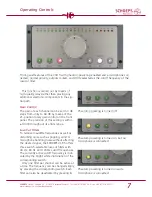
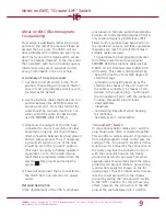
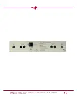
”Ground-Lift” Switch

Unit without
ground-lift switch

Conductive chassis

Conductive chassis

Circuit
ground

Hum current

Connection by
way of the house
AC safety ground

VSR 5 U

1

2

2

3

3

Connector
housing

Circuit
ground

I

Cable shield

The red dashed line is a ground
loop. As in the windings of a
transformer, magnetic fields--
either from power supply trans-
formers or due to differences in
chassis potential among con-
nected items of equipment –
cause current to flow at 50 or
60 Hz.

C*

Ground-lift
switch

”GND”

”LIFT”

”HI-Z”

1

* Bypass capacitor for RF; the 

SCHOEPS

K EMC _U cable also has bypass capa-
citors in its XLR plug

connector housing must be interrupted, and
this can again lead to problems with RFI.

To avoid both RFI and ground loops at the

same time, we recommend the use of the

SCHOEPS

K EMC _ U cable. In the connectors

of this cable there is no DC connection
between pin 1 and the housing; thus no
ground loops can occur. RFI on the other
hand is conducted to chassis ground through
condensers built into the plug connector.
This provides RF protection despite the lack
of a DC connection from pin 1 to the chassis.

So that the ”Ground-Lift” switch does not

create a ground loop, do not set it to the
”GND” position when this type of cable is
being used. The ”HI-Z” position of the
Ground-Lift switch is designed to bridge the
difference in ground potential among pieces

of equipment that are connected to power
outlets some distance apart, without causing
hum problems.

Safety is maintained by keeping the chassis

of the VSR 5 connected to AC safety ground
regardless of the ”Ground-Lift” switch setting.

Avoiding ground loops

The greater the size of the loop encompassed
by the relevant equipment, the greater the
effective AC magnetic field radiated by trans-
formers or electrical conductors, and the
stronger the induced hum is likely to be. Thus
to the extent possible, all interconnected
equipment that uses three-wire AC power
cords should be powered from the same out-
let. This will minimize the ground loop area
and thus the resulting hum.

The origin of ground loops

Summary of Contents for VSR 5 U

Page 1: ...VSR 5 U Microphone Preamplifier Operating Manual...

Page 2: ...2 SCHOEPS GmbH Spitalstr 20 D 76227 Karlsruhe Durlach Tel 49 0 721 943 20 0 Fax 49 0 721 495 750 www schoeps de mailbox schoeps de...

Page 3: ...3 SCHOEPS GmbH Spitalstr 20 D 76227 Karlsruhe Durlach Tel 49 0 721 943 20 0 Fax 49 0 721 495 750 www schoeps de mailbox schoeps de...

Page 4: ...rols 6 Notes on EMC Ground Lift Switch 9 Specifications 12 Safety Information 13 Warranty EMC Declaration of Conformity 14 2009 by Schalltechnik Dr Ing SCHOEPS GmbH SCHOEPS GmbH Spitalstr 20 D 76227 K...

Page 5: ...the unit by qualified service personnel If a fuse burns out during the warranty period the Dear customer Thank you for choosing the SCHOEPS VSR 5 a very high quality low noise low distor tion stereo m...

Page 6: ...nals of the corre sponding channel When activated the LED in the switch will glow brightly balanced micro phone output VSR 5 input socket The plug housing should not be connected to the cable shield p...

Page 7: ...d or microphone handling noise without affecting the desired signal the SCHOEPS VSR 5 offers three switch selectable low cut filters with 40 Hz 80 Hz and 120 Hz cutoff frequencies The currently active...

Page 8: ...schoeps de mailbox schoeps de button a second time The filter selection is stored when the preamplifier is turned off and is set automatically the next time the unit is turned on Level Indicator The...

Page 9: ...onding degree of immu nity to radio frequency interference RFI Filters for this purpose have been built into the inputs and outputs but these protective measures can reach their full effect only if su...

Page 10: ...en pin 1 and the housing thus no ground loops can occur RFI on the other hand is conducted to chassis ground through condensers built into the plug connector This provides RF protection despite the la...

Page 11: ...le should be cut But please be aware that doing this can lead to radio frequency interference especially if the RF is not bypassed to the chassis by way of a capacitor from pin 1 immediately at the in...

Page 12: ...6 dBu 132 8 dBV A RMS 117 4 dBu 119 6 dBV CCIR 1k Q peak Frequency range gain 30 dB 12 Hz 90 kHz 0 1 dB 2 5 Hz 400 kHz 3 dB Inter channel phase difference 0 0 at 5 Hz 0 0 at 50 Hz 0 0 at 1 kHz 0 0 at...

Page 13: ...e AC power cable is in good condition Arrange the AC power cable so that it will not be damaged and so that it does not cause accidents The unit is shipped with a three wire AC power cable with a Germ...

Page 14: ...purchase Please provide your bill of sale in all cases as proof of guarantee without it repairs will be undertaken only at the owner s expense We reserve the right to satisfy all warranty requirement...

Page 15: ...15 SCHOEPS GmbH Spitalstr 20 D 76227 Karlsruhe Durlach Tel 49 0 721 943 20 0 Fax 49 0 721 495 750 www schoeps de mailbox schoeps de...

Page 16: ...ange without notice Not responsible for errors or omissions 091101 Technik Schall SCHOEPS GmbH Spitalstra e 20 D 76227 Karlsruhe Durlach Tel 49 0 721 943 20 0 Fax 49 0 721 495 750 www schoeps de mailb...

Reviews: