


Note:
In the delivery package the restart interlock is not active. You must select this degree of protection (Wiring see
chapter 4.3), or else the OSSD outputs will not be released. If no degree of protection has been selected, the status
indication of the LEDs in the receiver will produce the following signal:
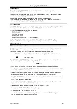
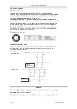
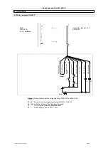
Activating the Restart Interlock
This operating mode can be selected via a cable wiring between the connections DIAG OUT and DIAG in.
DIAG OUT
DIAG IN
The electrical connection is described in the chapter Wiring diagram.
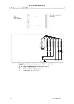
3.3.4 Relay monitoring (EDM)
This function monitors the triggered switch elements (auxiliary relay contacts) of the two outputs after each
interruption of the detection zone and before the restart (release) of the outputs. This helps to recognize
defective functions of the relays, e.g. smoldering of the contacts, rupture of the relay spring.
If the light curtain detects a defective function of the switch elements the outputs will be locked, i.e. a power
reset must be carried out after the correction.
When delivered, the relay monitoring function is not activated. This function can be activated using a
BUS converter NSR-0801, software >4.0 and a PC/Laptop. How to connect the cables is
described in chapter wiring diagram.
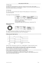
3.3.3 Testing
Test after Power ON
After switching Power ON, the system carries out a complete self and safety test within 2 seconds.
If the detection zone is uninterrupted, the system switches to ON.
If an error occurs, the outputs at the receiver will not switch ON. The OSSD OFF LED will flash to signal an
error message. For further information please refer to chapter 7.2 Error diagnosis.
Permanent self test
In the background, the system checks all safety functions within the cycle time. This time includes a check
of all functional components and a complete memory test.
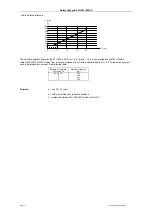
3.4 Diagnosis Window
Function
LED colour
Multi function
green
Blanking
blue
Signal receipt
orange
Restart
yellow
OSSD OFF
red
OSSD ON
green
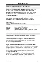
3.4.1 LED status information
SLG 422/ 425I-P
LED
Status LED
Description
OSSD ON
ON
Detection zone uninterrupted
flash
Diagnostic mode activated
OSSD OFF
ON
flash
Restart
ON
Signal receipt
ON/flash
ON/flash
OFF
Multi function
1 x blinken
Muting (entire protective field)
2 x blinken
Muting (only protective field acc. Teach)
3 x blinken
Muting via BUS control
4 x blinken
5 x blinken
Subject to technical changes
Page 3
LED OSSD OFF (red) + LED restart (yellow) flash
Safety light grid SLG 422/ 425I-P
function indication
Alignment between SLG* and ULS* is OK
res.
Beam coding A is active
detection zone area(s) are inactive (blanking)
input for control switch
Detection zone interrupted, system or configuration error
processing of the received signal
safety outputs signal status OFF
safety outputs signal status ON
Description
Start/Restart interlock active, signal expected at input Restart
Diagnostic mode activated, error message refer to Troubleshooting
Signal reception too weak; check alignment and installation height between
transmitter and receiver.
clean the black profile cover
SLG422/425I-P
Multi function
Blanking
Signal receipt
OSSD OFF
OSSD ON
Restart
protective area


