background image

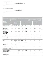
Table 1: Diagnostic information of the safety switchgear

Systemcondition
 

Magnet controlIN

LED

Safety outputs Y1,
Y2

Diagnostic
output OUT

Powerto
unlock

Power
to lock

green

red

yellow

AZM300Z AZM300B  

1)

 after 30 min: disabling due to fault

2)

 refer to flash code

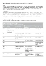
Table 2: Error messages / flash codes red diagnostic LED

Flash pulses
(red)

Designation

Autonomous
switch-off after

Error cause

1 flash pulse

Error (warning) at output
Y1

30 min

Fault in output test or voltage at output Y1,
although the output is disabled.

2 flash pulses

Error (warning) at output
Y2

30 min

Fault in output test or voltage at output Y2,
although the output is disabled.

3 flash pulses

Error (warning) cross-
wire short

30 min

Cross-wire short between the output cables
or fault at both outputs

4 flash pulses

Error (warning)
temperature too high

30 min

The temperature measurement reveals an
internal temperature that is too high

5 flash pulses

Actuator fault

0 min

Incorrect or defective actuator, bracket
broken

6 flash pulses

Fault rotary handle

0 min

Rotary handle not in authorised intermediate
position

Continuous red
signal

Internal error

0 min

Device defective

6.5 Solenoid interlock with serial diagnostic function SD

Solenoid interlocks with serial diagnostic cable have a serial input and output cable instead of the conventional
diagnostic output. If solenoid interlocks are wired in series, the diagnostic data are transmitted through the series-
wiring of the inputs and outputs.

Max. 31 solenoid interlocks can be wired in series. For the evaluation of the serial diagnostics line either the
PROFIBUS-Gateway SD-I-DP-V0-2 or the Universal-Gateway SD-I-U-... are used. This serial diagnostic interface is
integrated as slave in an existing field bus system. In this way, the diagnostic signals can be evaluated by means of
a PLC.

The necessary software for the integration of the SD-Gateway is available for download at products.schmersal.com.

The response data and the diagnostic data are automatically and permanently written in an input byte of the PLC
for each solenoid interlock in the series-wired chain. The request data for each solenoid interlock is transmitted to
the component through an output byte of the PLC. In case of a communication error between the SD-gateway and

Summary of Contents for AZM300B-I1-ST1P2P-A

Page 1: ...these operating instructions and that you know all applicable legislations regarding occupational safety and accident prevention prior to installation and putting the component into operation The mac...

Page 2: ...rer Detailed information regarding the range of applications can be found in the chapter Product description 1 5 General safety instructions The user must observe the safety instructions in this opera...

Page 3: ...g of movable safety guards F The safety switchgears are classified according to EN ISO 14119 as type 4 interlocking devices Designs with individual coding are classified as highly coded The different...

Page 4: ...concept of the control system in which the safety component is integrated must be validated to the relevant standards 2 4 Warning about misuse 2 In case of improper use or manipulation of the safety...

Page 5: ...on of risk maximum 200 ms Reaction time switching off safety outputs via actuator maximum 100 ms Reaction time switching off safety outputs via safety inputs maximum 1 5 ms General data Features Power...

Page 6: ...M6 Tightening torque of the fixing screws minimum 6 Nm Tightening torque of the fixing screws maximum 7 Nm Mechanical data Switching distances according EN IEC 60947 5 3 Nominal switching distance S...

Page 7: ...egree of pollution to IEC EN 60664 1 3 Electrical data Operating voltage minimum 20 4 VDC Operating voltage maximum 26 4 VDC Note Power supply general stabilised PELV power supply No load supply curre...

Page 8: ...mum 0 5 mA Voltage Utilisation category DC 12 24 VDC Current Utilisation category DC 12 0 25 A Voltage Utilisation category DC 13 24 VDC Current Utilisation category DC 13 0 25 A Test pulse duration m...

Page 9: ...valent safety level 2 The safety analysis of the guard locking function refers to the component solenoid interlock AZM as part of the complete system On the customer side further measures such as safe...

Page 10: ...as desired This device complies with the nerve stimulation limits ISED SPR 002 when operated at a minimum distance of 100 mm Changes or adjustments not expressly approved by K A Schmersal GmbH Co KG...

Page 11: ...l for the corresponding actuator 2 The actuator must be permanently fitted to the safety guards and protected against displacement by suitable measures tamperproof screws gluing drilling of the screw...

Page 12: ...presence of metal chips in the vicinity of the solenoid interlock is liable to modify the switching distance Keep away from metal chips Minimum distance between two solenoid interlocks as well as othe...

Page 13: ...er C2 Manual release by means of triangular key TK M5 The manual release must be protected against accidental actuation e g by using the enclosed seal after completing commissioning 3 3 Emergency exit...

Page 14: ...at it should only be used in an emergency The label can be used that was included in the delivery To activate the emergency release turn the red lever in the direction of the arrow to the end stop The...

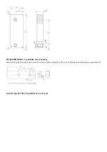
Page 15: ...3 5 Dimensions All measurements in mm AZM300 T T8 and N Device with emergency exit or emergency release Emergency exit T Emergency release N...

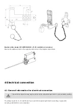
Page 16: ...Emergency exit T8 3 6 Actuator and accessories Actuator AZ AZM300 B1 not included in delivery Mounting plate MP AZ AZM300 1 available as accessory...

Page 17: ...MS AZ AZM300 B1 1 available as accessory Aluminium protective plate as a cover for use on glass and plastic doors on machines with high design requirements Lockout tag SZ 200 1 available as accessory...

Page 18: ...n cable release 4 Electrical connection 4 1 General information for electrical connection 2 The electrical connection may only be carried out by authorised personnel in a de energised condition The vo...

Page 19: ...drop on the cables and the current carrying capacity of the individual components F Accessories for the series wiring For convenient wiring and series wiring of SD components the SD junction boxes PF...

Page 20: ...n purposes The safety outputs of the first safety component are wired to the safety monitoring module The serial Diagnostic Gateway is connected to the serial diagnostic input of the first safety comp...

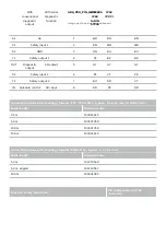
Page 21: ...X2 Safety input 2 6 PK VT PK Y2 Safety output 2 7 BU RD VT IN Solenoid control SD input 8 RD PK OR Connecting cables with coupling female IP67 IP69 M12 8 pole 8 x 0 25 mm to DIN 47100 Cable length Ord...

Page 22: ...enoid interlock If the voltage is not switched off within 5 minutes the solenoid interlock cancels the teach in procedure and signals a false actuator by 5 red flashes 4 Once the operating voltage is...

Page 23: ...lenoid interlock is locked when the IN signal 24 V is set 6 2 Mode of operation of the safety outputs In the standard AZM300Z variant the unlocking of the solenoid interlock causes the safety outputs...

Page 24: ...safety outputs to be disabled within the duration of risk After fault rectification the error message is reset by opening and re closing the corresponding safety guard Fault warning A fault that does...

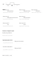
Page 25: ...fault GRA_CLI_kt syc03 Image not found or type unknown Safety guard locked GRA_CLI_ksym c77 Image not found or type unknown Lock GRA_CLI_ksym c76 Image not found or type unknown Unlock Evaluation of d...

Page 26: ...d not locked 24 V 0 V On Off Flashes 0 V 24 V 24 V Safety guard closed locking impossible 0 V 24 V On Off Flashes 0 V 24 V 0 V Safety guard closed and locked 0 V 24 V On Off On 24 V 24 V 24 V Error wa...

Page 27: ...handle not in authorised intermediate position Continuous red signal Internal error 0 min Device defective 6 5 Solenoid interlock with serial diagnostic function SD Solenoid interlocks with serial dia...

Page 28: ...the fault warning remains on for 30 minutes the safety outputs are also switched off red LED flashes see Table 2 Diagnostic error warning If an error warning is signalled in the response byte detaile...

Page 29: ...est including the following steps is recommended 1 Check for a secure installation of the actuator and the solenoid interlock 2 Check max axial misalignment of actuator and solenoid interlock 3 Check...

Page 30: ...8 2 Disposal 7 The safety switchgear must be disposed of in an appropriate manner in accordance with the national prescriptions and legislations...

Reviews: