3
AZ 415-../..
Operating instructions
Safety switch
EN
3. Mounting
3.1 General mounting instructions
The mounting holes are accessible after removal of the cover
The enclosure must not be used as an end stop Any mounting position
The mounting position however must be chosen so that the ingress of
dirt and soiling in the used opening is avoided
Mounting of the actuators:
See mounting instructions actuators
Please observe the remarks of the standards ISO 12100,
EN 953 and ISO 14119
The safety component and the actuator must be
permanently fitted to the safety guards and protected
against displacement by suitable measures (tamperproof
screws, gluing, drilling, pinning)
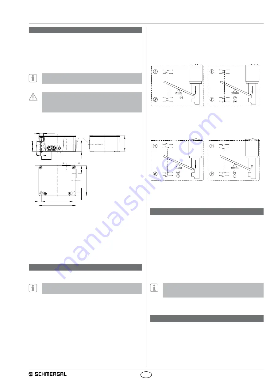
3.2 Dimensions
All measurements in mm
28
¤ 6,5
7,8
8
22,3
20
M20x1,5
8,8
A
88
84,6
46,5
103,6
26,8
29,5
¤ 11
Key
A Setting screw ball latch: 80-400 N
3.3 Adjustment
In the unlocked condition, the safety guard is kept in a closed condition
by the adjustable ball latch By rotating a hexagonal key wrench
clockwise, the desired holding force can be increased; if the hexagonal
key wrench is rotated counterclockwise, the holding force is decreased
The holding force must always be set as low as possible
4. Rear side Electrical connection
4.1 General information for electrical connection
The electrical connection may only be carried out by
authorised personnel in a de-energised condition
The contact labelling can be found in the wiring compartment of the
switch For the cable entry, suitable cable glands with an appropriate
degree of protection must be used Non-used input openings must be
sealed by means of threaded plugs After wiring, dust and soiling must
be removed from the wiring compartment
The conductors of the connecting cables must not obstruct the
movement of the switching lever.
Maximum tightening torque for the screws:
Cover 0.6 + 0.1 Nm; bottom cover 0.7 + 0.1 Nm
4.2 Contact variants
Contacts are shown with safety guard closed
AZ 415-11/11ZPK-M20
AZ 415-02/11ZPK-M20
S1
1 NO / 1 NC
S2
1 NO / 1 NC
S1
2 NC
S2
1 NO / 1 NC
21
13
21
13
22
14
22
14
S2
S1
21
13
11
21
22
14
12
22
S2
S1
AZ 415-02/20ZPK-M20
AZ 415-02/02ZPK-M20
S1
2 NC
S2
2 NO
S1
2 NC
S2
2 NC
13
23
11
21
14
24
12
22
S2
S1
11
21
11
21
12
22
12
22
S2
S1
Key
A
Positive break
P
Actuated
Q
not actuated
5. Set-up and maintenance
5.1 Functional testing
The safety function of the safety components must be tested
The following conditions must be previously checked and met:
1 Fitting of the safety switch and the actuator
2 Check the integrity of the cable entry and connections
3 Check the switch enclosure for damage
5.2 Maintenance
A regular visual inspection and functional test, including the following
steps, is recommended:
1 Check for correct installation of the actuator and the safety switch
2 Remove particles of dust and soiling
3 Check cable entry and connections
Adequate measures must be taken to ensure protection
against tampering either to prevent tampering of the safety
guard, for instance by means of replacement actuators
Damaged or defective components must be replaced.
6. Disassembly and disposal
6.1 Disassembly
The safety switchgear must be disassembled in a de-energised
condition only
6.2 Disposal
The safety switchgear must be disposed of in an appropriate manner in
accordance with the national prescriptions and legislations


