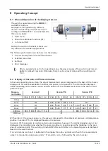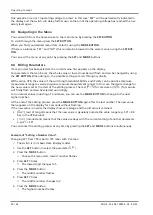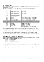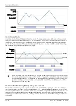
Description of Functions
26 / 44
EN-US · 30.30.01.00956 · 03 · 05/22
Description
Availability
See section
Zero point calibration
(> See ch. Calibrating the Vacuum Sen-
sor, Page 34)
Resetting HI/LO
(> See ch. Reset to Factory Settings, Page
34)
Reset counters
9.2 Measurement of Pressure and/or Vacuum
Depending on the version, the VSi-series switches measure the pressure and/or vacuum relative to the am-
bient air pressure:
•
VSi-V vacuum switch: The vacuum will be indicated as positive pressure difference.
•
Pressure switch VSi-P10: The pressure will be indicated as a positive pressure difference.
•
VSi-VP8 combined vacuum/pressure switch: Pressure is displayed as positive, vacuum is displayed as
negative. The measurement value via IO-Link process data is shown as a signed binary number. The
sign is indicated by the position of the decimal point on the display.
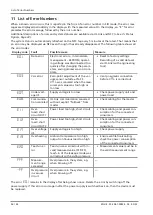
“FFF” appears on the display when the pressure is too high. In the case of versions P10 and VP8, an event
indicating that the measurement value is outside the valid range is also then sent via IO-Link.
The message “-FF” appears in the display when there is high vacuum and the appropriate IO-Link event
will be sent in the case of versions V and VP8.
In the IO-Link operation, these cases ensure that a fixed numerical value outside the normal measurement
range is transmitted instead of a measurement value (see “Special Values” in the data dictionary). These
numbers should not then be interpreted as measurement values but as an indicator of an overflow.
9.3 Monitoring the Operating Voltage
The switch measures the amount of its operating voltage US with a resolution of 100 mV.
When the valid voltage range is left, corresponding error statuses are triggered. In the undervoltage
range, the switch delays all inputs by the user.
The product is not a voltage meter! However, the measured values and the system responses
derived from them provide a helpful diagnostics tool for condition monitoring.
9.4 Switching Points
In the following, the switching point number is always denoted by an "x" when information
applies equally to both switching points. SPx therefore stands for both SP1 and SP2.
9.4.1 Switching Point Mode and Switching Point Logic
Both switching points are identical in terms of function and can be parameterized independently of one
another.
There are 4 different switching point modes to choose from:
•
Two-point mode H.no / H.nc
•
Window mode F.no / F.nc
•
Condition monitoring mode C.no / C.nc
•
Diagnostics mode D.no / D.nc
In this case, there is a differentiation between the switching point logic NO (normally open) and NC (nor-
mally closed). A change in the switching point logic from NO to NC causes a logical inversion of the elec-
trical switching outputs, the switching point bits in the IO-Link process data and the orange LED display(s)
on the switch.

