background image

Warranty

22 / 26

EN-US · 30.30.01.02107 · 00 · 07/19

8   Warranty

This system is guaranteed in accordance with our general terms of trade and delivery. The same applies to
spare parts, provided that these are original parts supplied by us.

We are not liable for any damage resulting from the use of non-original spare parts or accessories.

The exclusive use of original spare parts is a prerequisite for the proper functioning of the system and for
the validity of the warranty.

Wearing parts are not covered by the warranty.

Summary of Contents for SCTMc

Page 1: ...Mini Compact Terminal SCTMc Operating Instructions WWW SCHMALZ COM EN US 30 30 01 02107 00 07 19...

Page 2: ...ished thereby Repro duction of the contents in full or in part is only permitted within the limits of the legal provisions of copyright law Any modifications to or abridgments of the document are proh...

Page 3: ...epositing the Workpiece Part Blowing Off 10 3 3 Variants and product keys 10 3 4 Components of the Mini Compact Terminal 11 4 Technical Data 12 4 1 General parameters 12 4 2 Mechanical Data 12 4 2 1 P...

Page 4: ...01 02107 00 07 19 9 Spare and wearing parts accessories 23 9 1 Spare and Wearing Parts 23 9 2 Accessories 23 10 Decommissioning and Recycling 24 10 1 Disposing of the mini compact terminal 24 11 EC De...

Page 5: ...lure to heed these instructions If you still have questions after reading the technical documentation contact Schmalz service at www schmalz com services 1 3 Warnings in This Document Warnings warn ag...

Page 6: ...XY ejector AAA The type plate 2 contains the following data Part number Permitted pressure range Manufacturing date Serial number QR code Identical individual discs are installed in groups in the ter...

Page 7: ...ines Neutral gases are approved as evacuation media Neutral gases include air nitrogen and inert gases e g argon xenon and neon For further information see See ch Technical Data The product is intende...

Page 8: ...Assembly and maintenance work may only be carried out by qualified personnel The following target groups are addressed in this manual Installers who are trained in handling the product and can operat...

Page 9: ...l ejectors As an alternative there can also be a compressed air supply for each ejector 3 2 1 Suction of the Workpiece Vacuum Generation The ejector is designed for vacuum handling of airtight parts i...

Page 10: ...ts the vac uum from dropping If leaks cause the system vacuum to drop below the limit value configured for the switching point rP1 the venturi nozzle is switched back on 3 2 2 Depositing the Workpiece...

Page 11: ...sed Identical individual discs must be installed grouped together as blocks The combination of the optional functions External blow off EB and External vacuum EV cannot be selected 3 4 Components of t...

Page 12: ...chanical Data 4 2 1 Performance Data Type Nozzle 03 Nozzle 05 Nozzle 07 Nozzle 10 Nozzle size mm 0 3 0 5 0 7 1 0 Degree of evacuation 87 Max suction rate l min 1 2 2 7 5 15 28 Air consumption for suct...

Page 13: ...L3 X1 Y1 31 5 8 8 37 8 n 12 5 56 8 n 12 5 15 12 5 45 8 n 12 5 32 5 All dimensions given in millimeters mm The letter n stands for the number of ejector discs installed in the terminal The weight of o...

Page 14: ...66 5 H2 H3 H4 L L1 L2 L3 X1 Y1 31 5 8 8 38 5 n 12 5 56 8 n 12 5 15 12 5 45 8 n 12 5 32 5 All dimensions given in millimeters mm The letter n stands for the number of ejector discs installed in the te...

Page 15: ...s 1 Compare the entire delivery with the supplied delivery notes to make sure nothing is missing 2 Damage caused by defective packaging or occurring in transit must be reported immediately to the carr...

Page 16: ...ent materials that have been provided 2 Firmly connect and secure pneumatic and electrical line connections to the compact terminal 3 Ensure that there is adequate installation space in the area where...

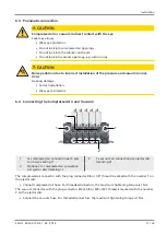
Page 17: ...ctors 6 4 Connecting the Compressed Air and Vacuum 1 1 2 3 1 1x compressed air connection per 9 ejec tor discs marking 1 2 1x vacuum air connection per ejector disc marking 2 3 Optional 1x compressed...

Page 18: ...cision The hose size and the thread on the connector depend on the particular ejector disc and can have the fol lowing dimensions Push in 8 6 Thread 1 8 thread female 4 Connect the compressed air hose...

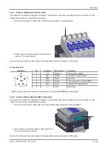
Page 19: ...Wire color 1 Function 1 US Brown 24 V power supply 2 IN1 White Suction signal input 3 GND Blue Ground 4 OUT Black Parts control output SP2 5 IN2 Gray Blow off signal input 6 Pink Not used 1 When usin...

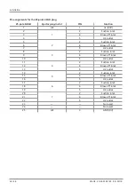
Page 20: ...let 4 5 H2 outlet 5 2 2 Suction inlet 6 4 Blow off inlet 7 5 H2 outlet 8 3 2 Suction inlet 9 4 Blow off inlet 10 5 H2 outlet 11 4 2 Suction inlet 12 4 Blow off inlet 13 5 H2 outlet 14 5 2 Suction inle...

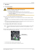
Page 21: ...ully functional 2 Check the device for visible damage and deal with any problems immediately or notify the supervi sor 3 Ensure that only authorized persons are present in the working area of the mach...

Page 22: ...es to spare parts provided that these are original parts supplied by us We are not liable for any damage resulting from the use of non original spare parts or accessories The exclusive use of original...

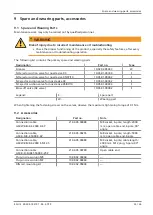
Page 23: ...ction valve for nozzle size 03 10 05 01 00382 S NC ejector suction valve for nozzle size 05 07 10 10 05 01 00394 S Blow off valve NC valve 10 05 01 00382 S Legend S Spare part W Wearing part When tigh...

Page 24: ...00 07 19 10 Decommissioning and Recycling 10 1 Disposing of the mini compact terminal 1 Dispose of the product properly after replacement or decommissioning 2 Observe the country specific guidelines...

Page 25: ...owing applicable EC directives 2014 30 EU Electromagnetic Compatibility 2011 65 EU Directive on the restriction of the use of certain hazardous substances in electrical and electronic equipment The fo...

Page 26: ...J Schmalz GmbH EN US 30 30 01 02107 00 07 19 Subject to technical changes without notice...

Reviews: