


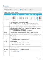
Device status code
The code shows the status of the device in terms of errors:
0 OK
Device status is OK.
1 Alert flagged
One or more alerts have been flagged. Please check the other alert fields to see the cause
of the alert. It can be one of the following sources:
◆
temperature alert
◆
input current alert
◆
output current alert
◆
input voltage alert
◆
output current drop alert
◆
input current drop alert
◆
sensor change alert
2 Setting(s) initialized
Some settings have been reset to default values. This may occur after a factory reset or a
firmware upgrade.
4 Power-on reset
The device has rebooted after a power loss. It can be one of the following reasons:
●
because of inserting the PDU power plug (mostly intentional. It can be
unintentional if someone removed the power plug accidentally)
●
because of a power outage (unintentional),
●
because of a defect in the internal power supply.
8 External reset
The device has been reset by pressing the reset button on the unit.
16 Watchdog timer
The device rebooted due to an internal error.
32 Brownout detected
Device rebooted because a voltage drop has been detected. This may indicate a defect in
the internal power supply or a dip in external power supply.
64 Controller error
A hardware error has been detected.
128 Slave reset
A communication issue has been detected with an outlet slave module.
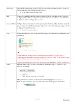
temperature alert
(1)
Temperature alert raises for temperatures, which exceed the user’s maximum temperature setting.
‘0’ indicates proper functioning.
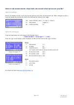
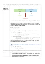
input overcurrent
alert
(1)
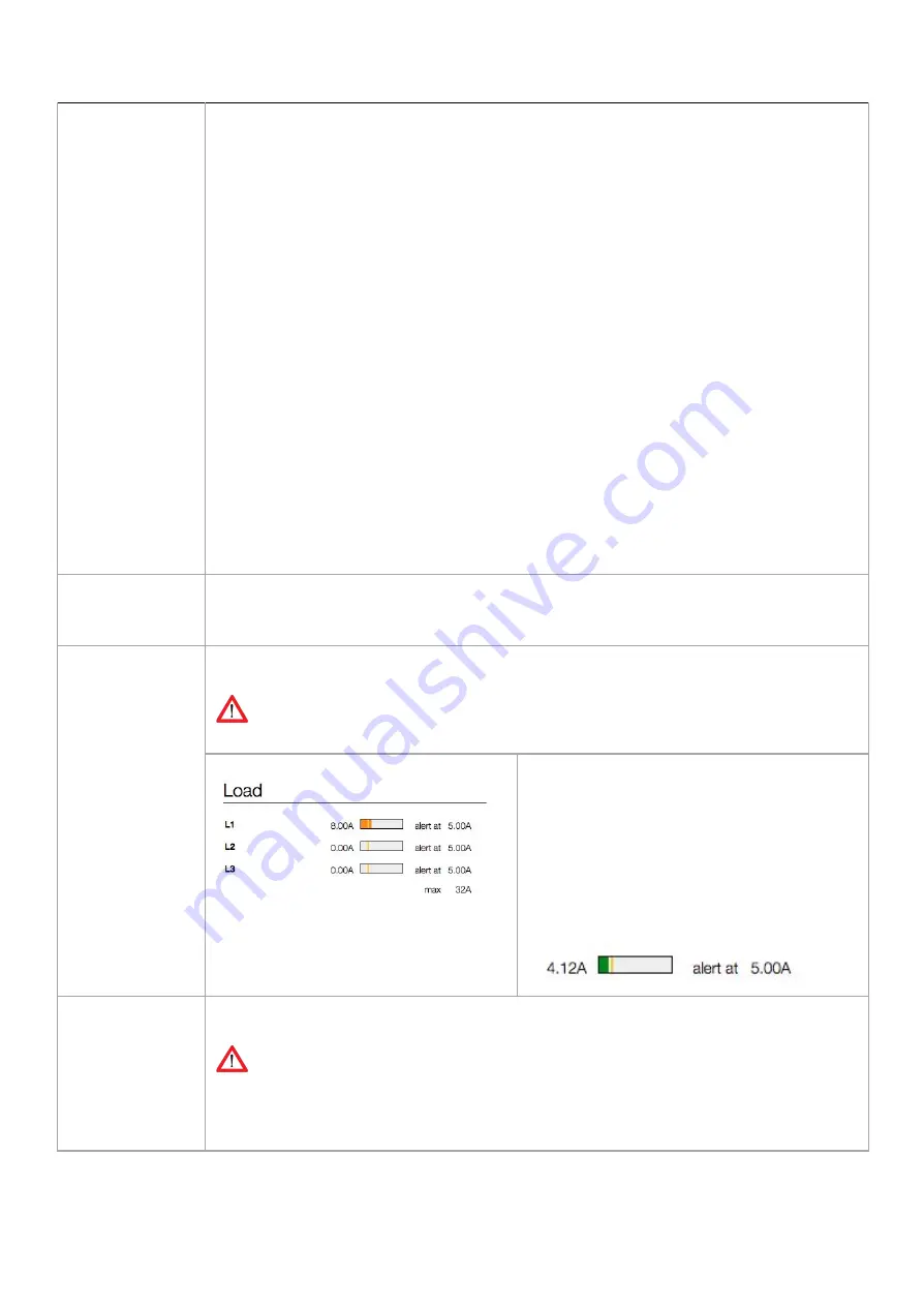
Input current alerts occur for inputs/lines/phases which exceed the user’s maximum current setting
for that input. When multiple inputs are in alert state, only the alert which appeared first is shown.
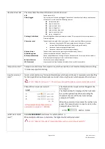
0 = OK , “Detected at input 1” => there is/was an input/line/phase current alert at phase/line 1
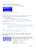
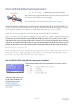
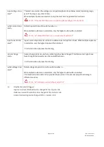
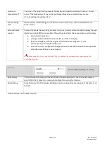
There still is an input overcurrent:
In the example above there still is an
overcurrent on input L1 => RED bar
The threshold of an input can be changed at the
tab < Input >.
The threshold itself is displayed in the horizontal
bar (vertical yellow line). When exceeding the
threshold, the color of the bar turns red (see
example on the left)
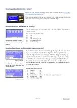
When the overcurrent is resolved, the red bar turns
green. This means there is an input current; in the
example below it is 4.12A
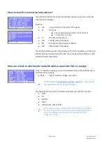
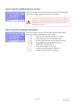
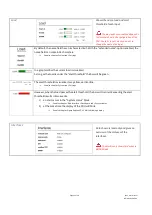
outlet overcurrent
alert
(1)-
Outlet
OVERCURRENT
alert raises for outlet number ..n.. .
When multiple outlets are in alert state, the highest outlet will be indicated
0 = OK , “Detected at outlet 9” means that there was a current drop at outlet “9”
Page 24 of 58
V262_User manual
Schleifenbauer PDU


