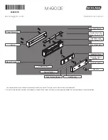
2
Features
Delayed Egress
Unlocking is delayed 15
seconds while an alarm sounds.
Automatic Voltage Selection
Magnet immediately detects
12VDC or 24VDC when power
is connected.
Fire Unlock
Input from fire system that will
unlock the magnet immediately.
Auxiliary Inputs
Allows use of an auxiliary switch
such as an exit device or push
button.
Alarm Output
Activates external alarm, when
in alarm state.
*Indicators
LED Status and Audible Alarm
*Magnetic Bond Sensor (MBS)
Detects proper bond between
magnet and armature. It can be
monitored remotely and locally
with an LED.
*Door Position Switch (DPS)
Indicates whether door is open
or closed. This feature is used
in conjunction with the MBS.
*Relock Time Delay
Relock time can be changed.
Range is 1 - 30 seconds.
*Door Prop Timer
Allows adjustment of the
amount of time a door can be
propped open before alarm
sounds. Range is 0 - 150
seconds.
* Plus Version Only
Models
M490DE (Single Lock Basic)
Delayed Egress, Automatic
Voltage Selection
M490DEP (Single Lock Plus)
Basic fe Magnetic Bond
Sensor (MBS), Door Position
Switch (DPS), Relock Time
Delay, Door Prop Timer, and
Indicators
M490DE-2 (Double Lock Basic)
Double lock with same features
as the Basic single lock
M490DEP-2 (Double Lock Plus)
Double lock with same features
as the Plus single lock
Notes:
• BOCA is a Plus only lock option.
• If BOCA option model is provided,
see page 12 for operational
description.
UL Requirements
• Units shall not impair operation of panic hardware mounted on door.
• Units shall not impair intended operation of an emergency exit.
• Not to be used without UL approved latching hardware.
• Units/Models are intended to be connected to UL Listed Equipment, not
intended for Burglar or Fire Alarm Initiating or Indicating Devices.
• Ambient Conditions - “For Indoor Use Only”.
• Wiring methods shall be in accordance with the National Electrical Code,
ANSI/NFPA 70.
•
This device complies with part 15 of FCC rules.
Operation is subject to following two conditions:
1. This device may not cause harmful interference.
2. This device must accept any interference received, including any
interference that may cause undesired operation. Changes or
modifications not expressly approved by party responsible for compliance
could void user’s authority to operate equipment.
Electrical Specifications
Model
M490DE
M490DEP
M490DE-2
M490DEP-2
Input Current @ 12VDC Input
.75ADC
1.25ADC
Input Current @ 24VDC Input
.45ADC
.76ADC
Holding Force Per Door Leaf
1500 lbs.
1500 lbs.
Size
3” x 12 1/2”
3” x 25 1/16”
Wire Gauge and Length Specifications
Max. Wire Length
Single Lock
Double lock
Wire Gauge 12VDC
24VDC
12VDC
24VDC
14
1000 feet
4000 feet
500 feet
2000 feet
18
400 feet
1600 feet
200 feet
800 feet
Warnings and Cautions
WARNING
Warnings indicate potentially hazardous conditions, which if not
avoided or corrected, may cause death or serious injury.
CAUTION
Cautions indicate potentially hazardous conditions, which if
not avoided or corrected, may cause minor or moderate injury.
Cautions may also warn against unsafe practices.
Pre-Installation Considerations
• Use ONLY the hardware provided for mounting this product
(NOTE: Non-standard Door thickness may require different sex nut
hardware - see specific instructions for required hardware).
• Follow the installation procedure as described in this manual.
• Check door thickness. If the door is not 1
C\v
” thick, a different sex nut
will be required. Contact customer service at 1-877-671-7011.
• Check door header. A minimum 2
C\v
” thick, flat surface is needed to
securely mount all screws for the magnet. If you do not have the
required surface, you will need filler plates and/or angle brackets to
properly mount the magnet.
Contact customer service at 1-877-671-7011.
Door: 1
C\v
” Thick
Header: At least
2
C\v
” thick, flat


