background image

OPERA

T

OR’S MANUAL

MAN 4163720

Rev

A

 10-2008

942221F

ZT219 19HP KAI W/52 SIDE DISCHARGE

942233F

ZT225 25HP KAW W/61 SIDE DISCHARGE

942244F

ZT225 25HP KAW W/52 SIDE DISCHARGE

942237F

ZT227 27HP KLR W/61 SIDE DISCHARGE

942248F

ZT221 21HP KAW W/52 SIDE DISCHARGE

942249F

ZT227 27HP KAW W/61 SIDE DISCHARGE

PARTS MANUAL 4163719

Summary of Contents for BOB-CAT 942221F

Page 1: ...HP KAI W 52 SIDE DISCHARGE 942233F ZT225 25HP KAW W 61 SIDE DISCHARGE 942244F ZT225 25HP KAW W 52 SIDE DISCHARGE 942237F ZT227 27HP KLR W 61 SIDE DISCHARGE 942248F ZT221 21HP KAW W 52 SIDE DISCHARGE 942249F ZT227 27HP KAW W 61 SIDE DISCHARGE PARTS MANUAL 4163719 ...

Page 2: ...tado de California hace saber que los gases de escape de los motores diesel y algunos de sus componentes producen cáncer defectos de nacimiento y otros daños en el proceso de reproducción humana L émission du moteur de ce matériel contient des produits chimiques que l Etat de Californie considère être cancérigènes provoquer des défauts congénitaux et d autres dangers en matière de reproduction El ...

Page 3: ...ollow all instructions and warnings completely Do not remove or defeat any safety features Make sure those who operate this machine are as well informed and careful in its use as you are See a Schiller Grounds Care Inc dealer for any service or parts needed Schiller Grounds Care Inc service ensures that you continue to receive the best results possible from Schiller Grounds Care Inc products You c...

Page 4: ...t manufacturemodifications and or accessories should personal injury and or property damage result MODEL NUMBER This number appears on sales literature technical manuals and price lists SERIAL NUMBER This number appears only on your mower It contains the model number followed consecutively by the serial number Use this number when ordering parts or seeking warranty information This symbol means AT...

Page 5: ...centage of riding mower related injuries Those operators should evaluate their ability to operate the riding mower safely enough to protect themselves and others from injury Do not carry passengers especially small chil dren They may fall off and be seriously injured Keep warning labels and this operator s manual legible and intact Replacement labels and manuals are available from the factory Do n...

Page 6: ... Starting Start only according to instructions in this manual or on the machine Before attempting to start the engine make sure the parking brake is on the PTO is disengaged the traction drive is in NEUTRAL When starting the engine make sure hands and feet are clear of the blades Do not start the machine while standing in front of the discharge chute or with the chute directed at someone Do not en...

Page 7: ...machine for damage and make repairs before restarting if the machine begins to vibrate abnormally Inspect and make repairs as needed before restarting except for repairs or adjustments as specifically noted such as for carburetor adjustment where the engine must be running Keep hands and feet clear of moving parts in these circumstances Allow the blades to come to a complete stop when stopping ope...

Page 8: ...accidents that sometimes lead to severe injury or death All slopes require extra caution Do not mow on slopes if uneasy or uncertain Ultimate reponsibility for safe operation on slopes rests with the operator Do not mow excessively steep slopes With ride on machines including articulated steering machines mow up and down slopes not across except for zero turn machines Zero turn machines should mow...

Page 9: ...WARNING SAFETY FUEL Gasoline and diesel fuels are flammable gasoline vapors are explosive Use extra care when handling Store only in containers specifi cally designed for fuel When refueling or checking fuel level Stop the engine and allow to cool Do not smoke Refuel outdoors only Use a funnel Do not overfill If fuel is spilled do not attempt to start the engine until the spill is cleaned up and v...

Page 10: ...iner near heating appliances with an open flame such as a water heater or an appliance with a pilot light Keep gasoline storage area free of grass leaves and excessive grease to reduce fire hazard Jump starting 1 Be sure the jumper cables are in good condition Turn off the ignition and all electrical accessories on both machines 2 Position the machine with a good charged bat tery next to but not t...

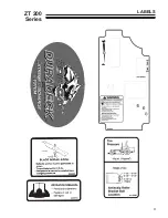
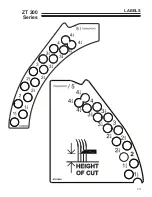
Page 11: ... 9 ZT 200 Series LABELS ...

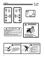
Page 12: ... 10 ZT 200 Series LABELS 4158400 ...

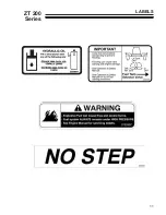
Page 13: ... 11 ZT 200 Series LABELS ...

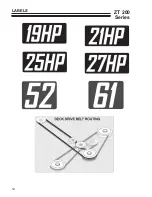
Page 14: ... 12 ZT 200 Series LABELS ...

Page 15: ... 13 ZT 200 Series 1 1 1 LABELS ...

Page 16: ... 14 ZT 200 Series LABELS ...

Page 17: ... 15 ZT 200 Series LABELS ...

Page 18: ...f whenever the machine is transported or stands unused for any length of time Shutting off the fuel supply avoids the possibility of flooding should any dirt get under the carburetor float needle Leaving the tank selector in either tank position can allow severe flooding which may ruin the engine by diluting the oil Right Tank Fuel flows from the right tank when the selector is turned 1 4 turn tow...

Page 19: ...e other is in forward By varying the relative positions of the two levers the rate of turn is varied to suit the mowing situation Slow down before making sharp turns The machine is capable of turning very rapidly when the levers are moved further apart from each other Loss of control and or turf damage may result Lift and traction levers operator s right side HEIGHT OF CUT PIN C Sets height of cut...

Page 20: ...LS FOOT LIFT PEDAL The foot lift pedal A allows the operator to raise the mower deck to the highest position without removing his her hands from the traction controls To use the foot lift pedal A press on it to raise the deck ...

Page 21: ...on each hydrostatic pump allow the machine to be pushed or towed without the engine running Raise the seat to gain access to these two valves U Turn both valves counterclockwise 1 turn to release the hydrostatic system Restore the hydrostatic system by turning the valves clockwise only until they re seat DO NOT overtighten Use caution if it is necessary to tow the machine With the bypass valves op...

Page 22: ...cooling fins governor parts and muffler Clean air intake screen Check air cleaner service if necessary ___ Never allow riders ___ Inspect area and remove stones branches or other hard objects that might be thrown causing injury or damage ___ Clean area around oil fill dipstick Remove dipstick and check to be sure oil is in operating range between marks on dipstick Add oil if necessary but Do Not O...

Page 23: ...e half open position and the choke to the OFF position OPERATOR PRESENCE Interlock System To start the engine The PTO switch must be OFF Both traction levers must be in the neutral lock position The parking brake must be ON To operate the machine 1 The operator must be in the seat or engaging the PTO will kill the engine 2 The parking brake must be OFF and the opera tor must be in the seat or movi...

Page 24: ...ne lever forward and one back Turns during forward movement Right turn move the right traction lever back toward neutral to slow the right drive wheel Left turn move the left traction lever back to ward neutral to slow the left drive wheel Turns during reverse movement Reverse right turn move the right traction lever forward toward neutral to slow the right drive wheel Reverse left turn move the l...

Page 25: ...hree rounds mow in the opposite direction left hand turns until finished If grass is extremely tall it should be mowed twice the first cut relatively high the second cut to the desired height Use the left side of the mower for trimming Choose cutting directions so that clippings are thrown onto areas that already have been cut This method results in the most even distribution of clippings and more...

Page 26: ... l p p A e r e h W X f f O p o T k c e h C l e v e L l i O X s k a e L r o F k c e h C X e k a t n I r i A n a e l C n e e r c S X r e n a e l C r i A n a e l C r e n a e l c e r P X r e n a e l C r i A n a e l C t n e m e l E X X s n i F g n i l o o C n a e l C X d n A l i O e g n a h C r e t l i F X a u n a m s r e r u t c a f u n a m e n i g n e e e S e c a l p e R k c e h C s g u l P k r a p S...

Page 27: ... ________________________________________________ ________________________________________________ L A R E N E G E T A D S R H E T A D S R H E T A D S R H E T A D S R H E T A D S R H E T A D S R H s e r u s s e r P e r i T k c e h C s t n i o P l l A e t a c i r b u L s t l o B s t u N k c e h C E N I G N E t n a l o o C e n i g n E k c e h C l e v e L e l b a c i l p p A e r e h W l e v e L l i O...

Page 28: ...or missing cotter pins Repair any other prob lems before operating Tire pressure Tires should be kept inflated at 14 lbs in2 1 0 kg cm2 Improper tire inflation can cause rapid tire wear and poor traction Uneven inflation can cause uneven cutting Overinflation of caster tires can cause casters to wobble on hard surfaces MAINTENANCE Battery Battery acid is caustic and fumes are explosive and can cau...

Page 29: ...aft 1 point 2 Deck lift pivots 6 points 3 Brake lever pivot 1 point 4 Push arms 2 points located at rear of cutterdeck under each fuel tank 5 Caster wheel pivots 2 points Lubricate every 500 hours or once a year NOTE ON BLADE SPINDLES The blade spindles on these machines use a superior sealed bearing that does not require relubrication ...

Page 30: ...aulic fluid and hydraulic filter after each 500 hours of operation using the same procedure given above NOTES View from right side View from below machine MAINTENANCE Before servicing the hydraulic system stop the engine disconnect spark plug wires and disengage the PTO After any hydraulic line is opened plug or cap it promptly to reduce the risk of contamination Do not use sealant tape on hydraul...

Page 31: ...dipstick before starting engine PERIODIC OIL CHANGES 1 See engine manual for oil and filter change inter vals after the break in period 2 Follow instructions for first oil change above Spark Plugs Remove each plug and check condition Good operating conditions are indicated if the plug has a light coating of grey or tan deposit A white blistered coating indicates overheating A black coating indicat...

Page 32: ...Disassemble air cleaner cover 2 Remove precleaner 3 Wash precleaner in kerosene or liquid detergent and water 4 Wrap precleaner in cloth and squeeze to remove cleaner 5 Saturate precleaner in engine oil Squeeze to remove excess oil 6 Re install precleaner Reassemble air cleaner components and screw assembly down tight Every 100 hours more often under very dusty or dirty conditions check the paper ...

Page 33: ...hart Uneven running lack of power or black exhaust fumes may indicate a dirty air cleaner To replace air cleaner elements 1 Unclamp end cover X and remove existing cleaner elements 2 Insert new elements Y and Z and replace cover Ensure the breathing port A is pointing down and towards the front of the tractor MAINTENANCE ...

Page 34: ... also reduces the risk of fire due to accumulation of combustible debris and chaff Brush or blow clippings and debris off the cutterdeck and engine deck WASHING MACHINE CAUTION Improperly washing a machine can cause water to enter bearings and other components This can greatly reduce component life Do not use a pressure washer Do not direct water at bearings or seals High pressure water can blow p...

Page 35: ...r 3 Install assembly on the blade spindle 4 Torque the blade bolt to 70 ft lbs BLADE REMOVAL Follow these instructions to prevent injury during blade removal 1 Loosen with a box wrench or a socket and long breaker bar To gain additional leverage slip a long pipe or thick walled tube over breaker bar or wrench 2 Insert wood block A as shown with grain perpendicular to blade to prevent blade from tu...

Page 36: ...at height 4 Loosen nuts I at all four corners of the deck NOTE This will relieve tension on chains H 5 Loosen the jam nuts E on the height of cut clips F and adjusting screws G Turn the adjust ing screws G until the play is taken out of the chains H at all four corners Tighten the jam nuts E against the clips F and at the adjusting screws G Retighten nuts I at this time COUNTERBALANCE SPRINGS 1 Ra...

Page 37: ...d for the height of cut desired To change the height of cut 1 Lift the deck to the highest position 2 Move pin N to the selected hole 3 Lower the deck until the lift lever is stopped by the pin NOTES Height of cut may vary due to the amount of tread on the tires tire diameter or inflation pres sure For best results adjust the rear deck rollers for the height of cut to be used see below FRONT DECK ...

Page 38: ...anical or hydraulic jacks 1 Remove rear wheels 2 Measure spring length O with parking brake N in the OFF position 3 Move parking brake N to the ON position and measure length of spring O again When spring deflects 3 8 it is properly adjusted 4 If adjustment is required return parking brake N to the OFF position 5 Disconnect one end of rod M at the brake and loosen jam nut 6 Adjust rod M in or out ...

Page 39: ...ck the turnbuckle jam nuts Run the engine up to high idle to check the adjustment Readjust if necessary 7 Repeat steps 5 and 6 for the opposite side 8 Remove the jumper wire J and reconnect the seat switch Reverse Return 1 Move traction levers out to the neutral lock posi tion and raise the seat 2 Locknut U should be run on the bolt as far as it will go 3 Loosen jam nut Y Adjust the clevis yoke by...

Page 40: ... from the wire har ness at plug P 4 Remove the carriage bolts securing torque re straint Q to clutch R Remove torque restraint 5 Remove old belt from the machine 6 Install a new belt by performing the these steps in reverse order ADJUSTMENTS TRACKING HANDLES An adjustment is provided to allow the operator to align the control levers with each other during opera tion 1 Turn knob W clockwise to shor...

Page 41: ...e cutterdeck belt see engine cutterdeck belt replacement Cutterdeck belt 1 Set the cutterdeck in the lowest height of cut position 2 Remove the engine cutterdeck belt from the deck idlers and pulley see engine cutterdeck belt replacement Push it aside but don t remove it from the machine 3 Run the cutterdeck belt off the idler as shown Remove it from the deck 4 Install the new belt by performing t...

Page 42: ...BOB CAT BUNTON RYAN STEINER SCHILLER GROUNDS CARE INC ONE BOB CAT LANE P O BOX 469 JOHNSON CREEK WI 53038 920 699 2000 www schillergc com ...

Reviews: