background image


B1051061 Rev. A 

  USBCam2 User Guide


14

3.1.4.  Auto Advance 

Auto Advance provides the capability of capturing multiple video 
images using only the camera’s handpiece. The sequence for view 
boxes is defined in the series itself or can be customized in the 
Series menu, under the Order item.  
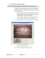
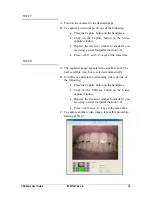
When the Video Capture window is open, pressing the handpiece 
Capture button does the following: 


Freezes and captures the current video image  


Displays the image in the small exam (the image occupies 
the same view box that was selected in the main exam) 


Advances automatically to the next available view box in the 
series. 

Clicking on a different view box makes it active and turns it to 
flashing green (default).   

3.1.5.  Delete 

Images in the small exam window can be permanently deleted using 
one of several options, as described below. 
3.1.5.1.


Drag and Drop (to trash icon) 

Images can be deleted, one at a time, by dragging-and-dropping 
them into the trash icon located on the video window. To delete an 
image, perform the following steps: 

1.  In the small exam window, click on the image to 

select it. 

2.  While holding down the left mouse button, drag the 

image into the trash icon. 

3.  Release the mouse button. 

4.  A message will prompt you to confirm that you 

wish to delete the image. Click Yes to delete the 
image. (Clicking No cancels the delete operation.) 

3.1.5.2.


Delete (right-click on image) 

1.  In the small exam window, click on the image to 

select it. 

2.  Right-click on the image to open a short context 

menu. 

3. Select Delete. 

4.  A message will prompt you to confirm that you 

wish to delete the image. Click Yes to delete the 
image. (Clicking No cancels the delete operation.) 

Summary of Contents for USBCam2

Page 1: ... User Guide B1051061 Sirona Dental Inc 30 30 47th Avenue Long Island City NY 11101 USA 718 937 5765 718 937 5962 fax Sirona Dental GmbH Sirona Straße 1 5071 Wals bei Salzburg Austria PART NUMBER B1051061 REV A ...

Page 2: ...Both US 5 912 942 US 5 841 126 US 6 456 326 US 6 549 235 US 6 570 617 US 6 744 068 US 7 369 166 CDR Wireless Sensors US 5 514 873 US 6 924 486 US 6 972 411 US 7 072 443 US 7 171 181 US 7 193 219 US D493 892 USBCAM US 6 002 424 US 5 908 294 Positioning Systems US 6 811 312 Schick WiFi US 7 090 395 6 091 982 Many of the designations used by manufacturers and sellers to distinguish their products are...

Page 3: ...OM 17 3 4 Acquiring Video Images with the Footpedal 20 3 5 Acquiring Video Images with Keyboard Shortcuts 20 4 Controls 21 4 1 Controls on the USBCam2 21 5 Protective Measures 22 5 1 Sheaths 22 5 2 Cleaning and Disinfecting the Handpiece 22 5 3 Recommended Disinfectant 23 5 4 Cleaning the Lens Surface 23 5 5 Cleaning the Computer 23 Appendix A Reference Information 24 A 1 Removal and Replacement P...

Page 4: ...og Box 31 Figure 10 Stream Format Dialog Box 32 List of Tables Table 1 Footpedal Actions 20 Table 2 Keyboard Shortcuts 20 Table 3 Description of Camera Controls 21 Table 4 Specifications 24 Table 5 Guidance and Manufacturer s Declaration Electromagnetic Emissions 25 Table 6 Guidance and Manufacturer s Declaration Electromagnetic Immunity 26 Table 7 Recommended Separation Distance Between Portable ...

Page 5: ...urns off the camera automatically after 5 minutes of continuous use The camera can be turned back on by simply pressing the ON OFF button on the handpiece Operate the USBCam2 as Directed Always use the USBCam2 in accordance with the directions and recommendations contained in this User Guide Do not attempt to modify the USBCam2 or use it in system configurations not specified in this document RF I...

Page 6: ... this requirement installers shall confirm that the USBCam2 is installed as described in this User Guide and shall perform the appropriate procedures therein Ensure Proper System and PC Workstation Installation and Operation The USBCam2 has been determined to be in accordance with international safety standards and is deemed suitable for use within the patient area which extends from the patient f...

Page 7: ...ry patient Protective sheaths are single use devices and must not be reused under any circumstance Reuse of single use devices instruments may cause them to become contaminated compromise their intended function and result in patient and user infection injury and or illness Recommended Order for Connecting Disconnecting Camera USB Cable Connect the USB cable to the camera handpiece before connecti...

Page 8: ...companying documents this User Guide for more information Conforms to European Union Medical Devices Directive MDD 93 42 EEC Indicates that this product meets North American safety standards The ETL mark is a Nationally Recognized Testing Lab NRTL marking and indicates conformance with UL 60601 1 and CAN CSA STD C22 2 NO 601 1 M90 Indicates that in the European Union at the end of product life thi...

Page 9: ... EN 50419 and in accordance with WEEE Directive 2002 96 EC This crossed out wheeled bin symbol on the product or on its packaging indicates that this product must not be disposed of with other unsorted municipal waste Instead it is user s responsibility to dispose of EE waste equipment by handing it over to a designated collection point for the reuse or recycling of waste electrical and electronic...

Page 10: ...cturer s date is placed on the equipment Information for Reuse Centers Treatment and Recycling Facilities As required by the WEEE Directive Sirona Dental or its Dealers will provide reuse treatment and recycling information for each type of new EEE put on the market within one year of the date in which the equipment is put on the market Information will include the different EEE components and mat...

Page 11: ...USBCam2 User Guide B1051061 Rev A ix USBCam2 USBCam2 with Handpiece Holder ...

Page 12: ...B1051061 Rev A USBCam2 User Guide x This page is intentionally left blank ...

Page 13: ...e pushbutton step Bright built in LEDs supply superior illumination and advanced optics provide excellent depth of field for optimal performance Adding USBCam2 to your office provides the following advantages Digital output over high speed USB 2 0 Full motion video full color depth and VGA resolution quality with no compression artifacts Plugs directly into your computer no separate power supply r...

Page 14: ... accidental damage The holder also turns off the camera automatically when the handpiece is stored When the handpiece is removed the camera is turned on automatically and is ready for use A programmable button to Freeze Take Unfreeze video is located at the side opposite from the camera LEDs near the middle of the handpiece Figure 7 Built in support for these video functions is provided by compati...

Page 15: ...Whether image optimization is enabled or not depends on the capabilities of the video card installed on your system While most newer systems have video cards that will support image optimization some older systems may not In the event image optimization is not enabled for your system please check our website http www schickbysirona com for a current listing of video cards that support this feature...

Page 16: ...rectXfileson yoursystem Proceduresforinstallingthesefiles can befoundinthissection The software for your USBCam2 consists of the following components USBCam2 Device Driver Installation DirectX Update You must install each of these components successfully to ensure proper operation of your USBCam2 Actual installation differs slightly between operating systems Windows Vista and Windows XP so you sho...

Page 17: ...er CD If the start page doesn t start automatically click Start Run and enter d CDR USBCam 2 Driver Setup if your drive letter is different use that one instead B At the User Account Control window select Allow I trust this program C If prompted install Microsoft s NET framework D At the Welcome screen click Next STEP 3 A Choose Complete This is the recommended installation and is appropriate for ...

Page 18: ...station B If prompted install Microsoft s DirectX STEP 6 A Click Finish B Connect the USBCam2 camera to your computer For details refer to Section 2 5 C After a few seconds the message Device driver software installed successfully will appear momentarily in the Windows System tray D Remove USBCam2 Driver CD ...

Page 19: ...m2 Driver CD If the setup doesn t start automatically click Start Run and enter d CDR USBCam 2 Driver Setup if your drive letter is different use that one instead B At the start page click the Install USBCam2 Driver button C If prompted install Microsoft s NET framework D At the Welcome screen click Next STEP 3 A Choose Complete This is the recommended installation and is appropriate for most cust...

Page 20: ...your workstation B If prompted install Microsoft s DirectX STEP 6 A Click Finish B Connect the USBCam2 camera to your computer For details refer to Section 2 5 C The message Your new hardware is installed and ready to use will appear momentarily in the Windows System tray D Remove USBCam2 Driver CD ...

Page 21: ... the other Figure 1 The A type connector fits any available USB port on the computer The B type connector fits the handpiece For EMC and EMI compliance the USB cable should not exceed a maximum length of 5 meters 5 5 yards Figure 1 USB Cable Connectors As a final check that your USBCam2 is ready for use open the Device Manager Windows Start Control Panel System Device Manager In Device Manager exp...

Page 22: ...unit willprovidethebestall around solution 2 6 1 Dental Unit Option To install the handpiece holder Figure 3 to a standard inch instrument bar perform the following steps 1 Remove the handpiece from its holder before performing this procedure 2 Remove the cutout block from the holder by untightening and retaining 2 Phillips screws 3 Attach the holder to the instrument rail mounting block by tighte...

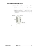
Page 23: ...ng steps 1 Remove the handpiece from its holder before performing this procedure 2 Position the holder on a smooth stable vertical surface 3 Using the holes on the back of the holder as guides fasten the holder securely to the wall using 2 6 x 3 4 dry wall screws not supplied or other hardware appropriate to the mounting surface Figure 4 Handpiece Holder Wall Mounting Installation ...

Page 24: ...camera by clicking the Power On Off button Figure 7 item 2 Removing the handpiece from its holder also turns the camera on 3 1 2 Turning the Camera Off When the camera s light is on clicking the camera s Power On Off button Figure 7 item 2 shuts power off to the camera Clicking the Power On Off button restores power to camera and turns the LEDs back on When not in use store the camera in its holde...

Page 25: ...e following 1 Press the Capture button on the camera handpiece or click on the Capture button in the Video Capture window The captured image is displayed in the small exam and the next available viewbox is selected automatically 2 Press the Capture button on the camera handpiece again or click the Unfreeze button in the Video Capture window 3 Repeat the previous steps to capture additional video i...

Page 26: ...the small exam window can be permanently deleted using one of several options as described below 3 1 5 1 Drag and Drop to trash icon Images can be deleted one at a time by dragging and dropping them into the trash icon located on the video window To delete an image perform the following steps 1 In the small exam window click on the image to select it 2 While holding down the left mouse button drag...

Page 27: ... the Video capture window is open Figure 6 It refers to the automatic correction of distortion created by the lens barrel of the camera This distortion may skew the image slightly around the borders there are no other effects on video quality Whether image optimization is enabled or not depends on the capabilities of the video card installed on your system While most newer systems have video cards...

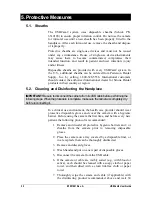
Page 28: ...n dispose it of properly Protective sheaths are single use devices and must not be reused under any circumstance Reuse of single use devices instruments may cause them to become contaminated compromise their intended function and result in patient and user infection injury and or illness When the sheath is inserted over the handpiece notice that the upper part of the sheath covering the lens has b...

Page 29: ... 3 Enter the appropriate patient information and then click on Video Series You may use a pre defined video series or create a new one 1 If you choose to create a new video series click Edit Series which opens the New Custom Video Series dialog box The numbers in the text boxes correspond to how many view boxes are included in this series You can edit the numbers in the text boxes creating a serie...

Page 30: ...ted click on it again to begin viewing live video or right click on the selected view box and select Capture Video STEP 6 A The video capture window displays live video A smaller version of the exam window is also displayed B The view box that was selected in the main exam flashes green in the small exam Clicking on a different view box will make that one active instead ...

Page 31: ...n 3 4 Press ALT and C keys at the same time STEP 8 A The captured image appears in the smaller exam The next available view box is selected automatically B To unfreeze and return to streaming video do one of the following Press the Capture button on the handpiece Click on the Unfreeze button in the Video capture window Depress the Green or Amber footpedal if you are using a serial footpedal Sectio...

Page 32: ...eaming Freeze Image Green or Amber Still Image is frozen in video window Unfreeze Image Green or Amber 3 5 Acquiring Video Images with Keyboard Shortcuts Video image acquisition can be also accomplished though the use of shortcut keys To use the following shortcuts press and hold down the first key always the Alt key and then press the second key shown after the plus sign for the appropriate actio...

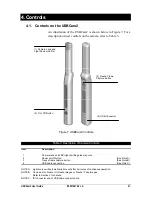
Page 33: ...amera lens and LED light emitting diode source 2 Power on off button See Note A 3 Freeze frame capture button See Note B 4 USB cable connection See Note C NOTE A Light source will automatically time out after 5 minutes of continuous operation NOTE B Can be set to Freeze Unfreeze images or Freeze Take images Refer to Section 3 for details NOTE C B connector end of USB cable connects here 1 Camera L...

Page 34: ...nd Disinfecting the Handpiece IMPORTANT Be sureto disconnect thecamerafromitsUSBcablebeforeperformingthe followingsteps Whentheprocedure is complete makesure thecamera iscompletelydry beforereconnectingit In a clinical use environment the health care provider should wear protective disposable gloves and cover the camera with a hygienic barrier Before using the camera the first time and before ever...

Page 35: ...nfection and is available from Patterson Dental and other suppliers Cavi Wipes Metrex Research Kerr or equivalent 5 4 Cleaning the Lens Surface IMPORTANT Beforecleaningthelens makesureit isfreeof anyabrasivecontaminants asthis willhelppreventthe formationof scratchesduringcleaning To clean the lens surface moisten a soft cotton swab dipped in rubbing isopropyl alcohol Gently wipe the lens surface ...

Page 36: ...neral Requirements for Safety IEC60601 1 2 Medical Electrical Equipment Part 1 General Requirements for Safety 2 Collateral Standard Electromagnetic Compatibility Requirements and Tests UL60601 1 Medical Electrical Equipment General Requirements for Safety Input electrical rating 5VDC 440mA Transport and storage conditions Ambient temperature range 0 F 18 C to 150 F 66 C Relative humidity range le...

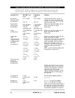
Page 37: ...e should not exceed a maximum length of 5 meters 5 5 yards Cables longer than that distance may result in increased emissions or decreased immunity Table 5 Guidance and Manufacturer s Declaration Electromagnetic Emissions PLEASE NOTE The USBCam2 is intended for use in the electromagnetic environment specified below The customer or user of the USBCam2 must ensure that it is used in such an environm...

Page 38: ...1 5 UT 95 dip in UT for 0 5 cycle 40 UT 60 dip in UT for 5 cycles 70 UT 30 dip in UT for 25 cycles 5 UT 95 dip in UT for 5 sec 5 UT 95 dip in UT for 0 5 cycle 40 UT 60 dip in UT for 5 cycles 70 UT 30 dip in UT for 25 cycles 5 UT 95 dip in UT for 5 sec Mains power quality should be that of a typical commercial or hospital environment If the user of the USBCam2 requires continued operation during ma...

Page 39: ...ects and people a Field strengths from fixed transmitters such as base stations for radio cellular cordless telephones and land mobile radios amateur radio AM and FM radio broadcast and TV broadcast cannot be predicted theoretically with accuracy To assess the electromagnetic environment due to fixed RF transmitters an electromagnetic site survey should be considered If the measured field strength...

Page 40: ...m output power of the transmitter W Separation distance according to the frequency of the transmitter m 150 kHz to 800 MHz d 1 2 x P 800 MHz to 2 5 GHz d 2 3 x P 0 01 0 12 0 23 0 1 0 38 0 73 1 1 2 2 30 10 3 8 7 3 100 12 0 23 00 For transmitters rated at a maximum output power not listed above the recommended separation distance d in meters m can be estimated using the equation applicable to the fr...

Page 41: ...n verify the amount of video memory available on your graphics card STEP 1 A At the Windows desktop click Start Run and then type dxdiag exe B The DirectX Diagnostic Tool dialog box is displayed C Under the System tab verify that your current DirectX version is 8 1 or higher STEP 2 A If your DirectX version is 8 1 or higher you have the correct version for USBCam2 operation Click Exit to close thi...

Page 42: ...ed other video drivers with a video capture card for example they can be selected from this drop down box Video Settings More camera operation and video displays options are available here Customizable settings for Camera Properties and Video Format are provided on the pages that follow There are no user selectable settings on the Display dialog which has been omitted Image Optimization Indicates ...

Page 43: ...ked factory setting Shutter Speed Auto 1 factory setting White Balance Fixed Mode 1 factory setting AGC checked factory setting Mirror unchecked factory setting Edge Enhancement Horiz checked factory setting Vert checked factory setting Backlight Compensation Enable backlight compensation unchecked factory setting Region width 1 8 factory setting Region height 1 8 factory setting ...

Page 44: ...0 Stream Format Dialog Box Table 10 Stream Format Dialog Box Description Item Description Video Format Video Standard None Frame Rate 29 970 may vary Flip Horizontal unchecked Color Space Compression UYVY Output Size 640 x 480 Compression no data ...

Page 45: ...ze in Video Format dialog box Camera is not connected to High Speed USB 2 0 port Reconnect camera to appropriate port 4 Spots are visible on video image Check camera lens for spots and follow the instructions in the Handpiece and Lens cleaning section of this document Section 5 4 Also check the fit of the camera sheath over the lens A camera sheath should be on tight enough so that there are no wr...

Page 46: ...ures 24 RF Interference iii S Safety Issues Always Use Sheaths with Sensors v Avoid Excessive Temperatures iii Check USBCam2 before Using iii Connecting Disconnecting USB Cables v Disconnect Camera from USB Cable before Cleaning and Disinfecting v Ensure USBCam2 Operates Optimally iv Items Not Part of the System iv Operate the USBCam2 as Directed iii Proper PC Workstation Cleaning Methods v Proper...

Page 47: ...USBCam2 User Guide B1051061 Rev A 35 W Waste Electrical and Electronic Equipment WEEE vii ...

Reviews: