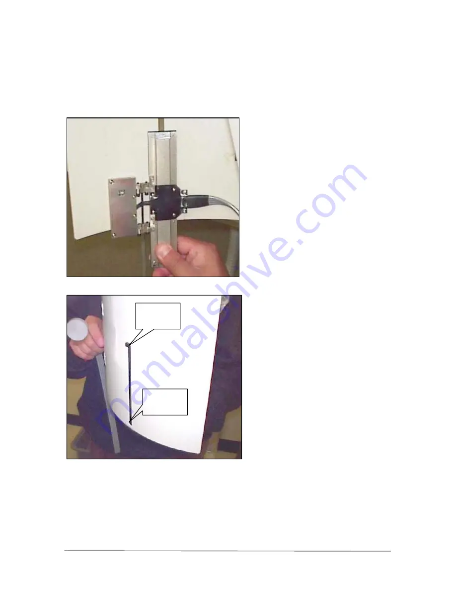
3.2. Install Sensor Assembly
Carefully slide sensor assembly into faceplate until upper guide is seated firmly at top of aperture slit and lower guide fits in bottom of aperture.
UPPER GUIDE
LOWER GUIDE
B1051105 Rev. –
Rotograph Installation
8
Page 1: ...STEMS Installation Instructions for Villa Rotograph Schick Technologies Inc 31 00 47th Avenue Long Island City New York 11101 718 937 5765 718 937 5962 FAX Part Number B1051105 Rev F GENERAL DEPTS QA DOCUMENT B1051105Rev doc ...
Page 2: ...heir products are claimed as trademarks Where those designations appear in this document and Schick Technologies Inc was aware of a trademark claim the designations have been printed in caps or initial caps Part Number B1051105 Rev September 12 2000 Printed in the United States of America This document was originally prepared in English ...
Page 3: ...ver Plate 7 3 2 Install Sensor Assembly 8 3 3 Install Sensor Clip 9 3 4 Route Sensor Cable 10 3 5 Check Sensor Cable Run 11 3 6 Install Codestrip Assembly 12 3 7 Install Interlock Defeater 13 3 8 Secure Sensor Assembly 15 3 9 Check Codestrip Alignment 16 3 10 Reinstall Rotation Arm Cover Plate 18 4 Remote Module Power Supply and PCI Board 19 4 1 Install Remote Module 19 4 2 Install Power Supply 20...
Page 4: ...ns can be found in the CDRPan User s Guide Mechanical Considerations The sensor package the remote module and the cables of the CDRPan system are mounted outside of the patient area to ensure patient safety and reliable equipment operation Radiation Concerns No adjustments or alterations are made to the X ray source of the panoramic equipment B1051105 Rev Rotograph Installation ii ...
Page 5: ...ard P N B3301100 and cable B2211001 The CDRPan system requires the following software CDR software version 2 1 or higher CDRPan installation disk which includes the PCI board device driver and the series set to be used with panoramic exams 1 3 Overview for Installing CDRPan This Installation Manual is one of two documents you will need to install the CDRPan system completely After performing the i...
Page 6: ...m is operating properly B Familiarize yourself with the installation steps before performing them C Determine the location of your computer This will be useful when you install the Remote Module and need to run cables between it and your computer ROTATION ARM X RAY SOURCE FACEPLATE Figure 1 Picture of the Villa Rotograph B1051105 Rev Rotograph Installation 2 ...
Page 7: ...em To perform the installation procedures in this manual you will need the following CDRPan parts and assemblies A Sensor Assembly B Curved Cassette Codestrip Assembly A Mounting Clip B and Interlock Defeater C B A C Rotograph Installation B1051105 Rev 3 ...
Page 8: ...C Remote Module D Cable Holders and Clamps E Power Supply B1051105 Rev Rotograph Installation 4 ...
Page 9: ...F PCI Board G Data Cable for PCI Board H X ray Filter and Allen Keys Rotograph Installation B1051105 Rev 5 ...
Page 10: ...wdriver to remove and replace rotation arm cover plate and to install sensor clip codestrip assembly and interlock defeater B Allen wrench hex key 3 32 in to adjust clearance between encoder and codestrip C Allen wrench hex key 0 050 in to secure sensor clip B1051105 Rev Rotograph Installation 6 ...
Page 11: ...3 Sensor and Codestrip 3 1 Remove Rotation Arm Cover Plate Using a Phillips screwdriver remove screw from bottom of plate and remove plate from rotation arm Rotograph Installation B1051105 Rev 7 ...
Page 12: ... Assembly Carefully slide sensor assembly into faceplate until upper guide is seated firmly at top of aperture slit and lower guide fits in bottom of aperture UPPER GUIDE LOWER GUIDE B1051105 Rev Rotograph Installation 8 ...
Page 13: ...the bottom of the aperture and secure it in place using the Allen key 050 in to tighten 2 screws CAUTION Light tension on the set screws is all that is needed to secure the sensor clip Do not apply excessive torque Rotograph Installation B1051105 Rev 9 ...
Page 14: ...ute sensor cable to the top of the panoramic machine Allow enough slack in the cable for the rotation arm of the panoramic machine to move freely Sensor cable secured along faceplate Sensor cable secured across faceplate B1051105 Rev Rotograph Installation 10 ...
Page 15: ...n Swivel the arm of the panoramic machine to ensure there is enough slack in the cable for the rotation arm to move freely Adjust cable if necessary Sensor cable secured along rotation arm Rotograph Installation B1051105 Rev 11 ...
Page 16: ...he codestrip assembly on the drum cassette holder by tightening screws with a Phillips screwdriver B Align the codestrip assembly with the encoder window CODESTRIP CASSETTE HOLDER CODESTRIP ENCODER WINDOW B1051105 Rev Rotograph Installation 12 ...
Page 17: ... Interlock Defeater A Slide the interlock defeater onto the drum cassette holder Make sure that it fits over and depresses the interlock limit switch on the panoramic machine Rotograph Installation B1051105 Rev 13 ...
Page 18: ...B When the interlock defeater is firmly in place secure it to the cassette holder using a Phillips screwdriver to tighten 4 screws B1051105 Rev Rotograph Installation 14 ...
Page 19: ...mbly Adjust the encoder section of the sensor assembly to approximately 1 mm from the codestrip on the drum cassette Use the Allen key 3 32 in to tighten the hinge links on the encoder Rotograph Installation B1051105 Rev 15 ...
Page 20: ...nt The proper distance between these two parts should be approximately 1 mm when the arm of the panoramic machine is rotated Verify this distance at the start and at the end of motion Start of Panoramic Motion End of Panoramic Motion B1051105 Rev Rotograph Installation 16 ...
Page 21: ...ip assembly for proper alignment As in the previous step recheck the distance between the encoder and the codestrip At the start and end of motion the distance should be approximately 1 mm SHIM Rotograph Installation B1051105 Rev 17 ...
Page 22: ...3 10 Reinstall Rotation Arm Cover Plate A Reinstall cover plate B Proceed to Chapter 4 to continue with CDRPan system installation B1051105 Rev Rotograph Installation 18 ...
Page 23: ...Apply velcro to the top of the panoramic machine along the top edge of the rotational arm This will make it easy to see the status lights on the module B Apply velcro to the bottom of the remote module also and mount the remote module to the panoramic machine C Connect the sensor cable to the remote module Then use a small screwdriver to tighten the screws on the 37 pin connector D The cables on t...
Page 24: ...panoramic machine C Connect the connector cable to the remote module D Plug the power supply cable into a wall outlet 4 3 Install PCI Board 4 3 1 Tools and Materials To install the PCI board you will need a small screwdriver to remove the cover from your computer to secure the PCI board in its slot and to secure one end of the data cable to the remote module and the other end to the PCI board 4 3 ...
Page 25: ...driver to tighten the screws on the connector E Connect the other end of the data cable to the remote module Then use a small secrewdriver to tighten the screws on the connector F Refer to the CDRPan User s Guide P N B1051008 to continue with CDRPan system installation Rotograph Installation B1051105 Rev 21 ...
Page 26: ...Other items as needed Power Supply Placed at base of host machine Connects to Remote Module and wall power source Remote Module Secured to top of host machine Connects to Sensor Assembly CDRPan PCI card and Power Supply Sensor Assembly Mounted to faceplate aperture Connects to Remote Module Figure 2 Installing CDRPan on Curved Cassette Type Machine B1051105 Rev Rotograph Installation 22 ...