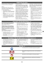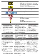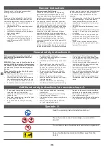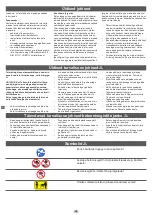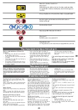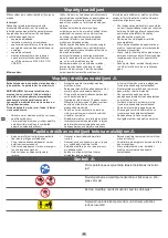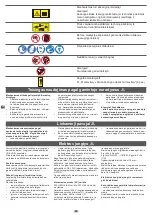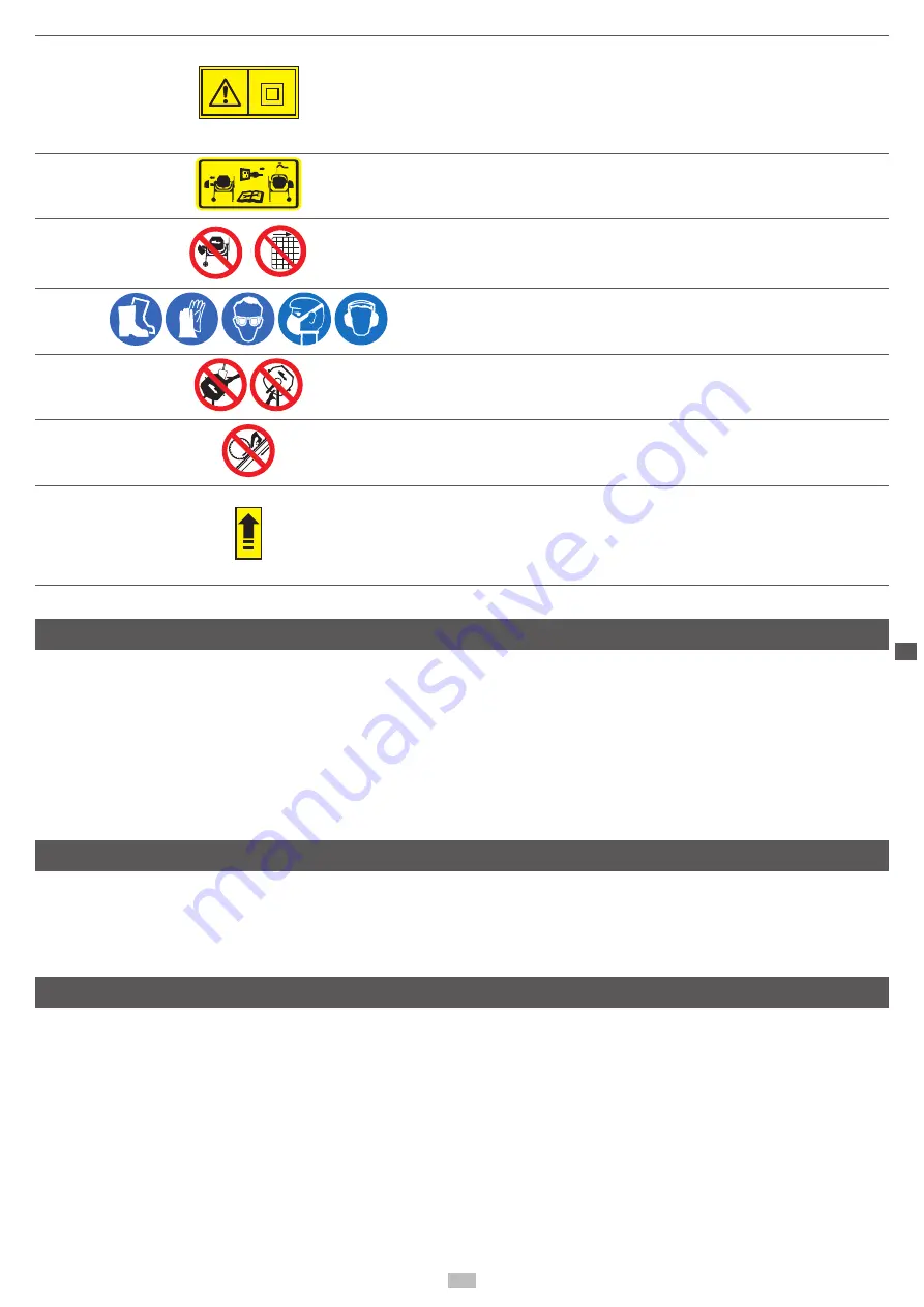
The machine has protective insulation!
Caution!
The protection class is retained only if original insulating
material is used during maintenance and the insulation dis-
tances are not changed.
Pull the power plug out before cleaning or maintenance!
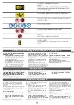
Size: 20 (mm) 40 (mm)
Ø 25 mm
129 x 70
The concrete mixer can be operated only with fully closed
protection device!
Wear protective clothes!
Do not put your hands into the moving drum!
Caution!
Risk of getting crushed at the sprocket
Installation help!
See: Installation, installing the upper section of the drum
(Fig.6)
Correct use according to manufacturer´s instructions
m
The machine corresponds to the applicable
EC Machine Directive.
•
The concrete mixer is intended exclusively
for private use at home and in the garden.
•
It should be operated only within the frame
-
work of the technical data.
•
The concrete mixer is meant exclusively for
the production of concrete and mortar.
•
The applicable accident prevention rules
and the other generally recognised techni
-
cal safety regulations must be observed.
•
The machine may be used, serviced or
repaired only by persons who are familiar
with it and are instructed about its risks.
Arbitrary alterations in the machine will free
the manufacturer from any liability for the
resulting damage.
•
The machine is to be used only with the
manufacturer’s original accessories and
original tools.
•
Any use that goes beyond this will be
treated as improper use. The manufacturer
will not be responsible for damage resulting
from improper use; the risk will be borne
solely by the user.
Caution! The Following Actions are Forbid-
den:
Operation in atmosphere that is exposed to
the risk of explosion
Use in the food products industry
Mixing explosive, combustible and health-
endangering substances.
Residual risks
m
The machine is built on the basis of the
latest technology and in accordance with the
recognised technical safety rules. Never-
theless, individual residual risks can occur
while working.
•
Risk of injury from rotating parts
•
Risk from power where improper electrical
connecting cables are used
•
Further, indeterminate residual risks may
remain even after taking all relevant pre
-
ventive measures.
•
Residual risks can be minimised if the sa
-
fety instructions and conditions for proper
use, as well as the operating instructions,
are observed
Electrical connection
m
The installed electric motor is connected in
operation-ready condition. The connection
corresponds to the common VDE and DIN
provisions.
The customer-side mains connection, as well as
the used extension cable, must correspond to
these specifications.
Important Instructions
In case of overload, the motor is switched off
automatically.
•
The motor can be activated again after a
cooling period (different times for different
models).
Damaged Electrical Connecting Cables
Electrical connecting cables frequently experi
-
ence insulation damage.
The causes are:
•
Pressure points, if connecting cables are
routed through windows or doors.
•
Kinks, due to improper mounting or routing
of the connecting cables.
•
Cuts due to connecting cables being run
over.
•
Insulation damages due to tearing away
from the wall socket.
•
Cracks in insulation due to ageing. Such
damaged electrical connecting cables
should not be used, they can be fatal due to
damaged insulation!
Check electrical connecting cables regularly
for damage. Ensure that when checking the
connecting cable, it does not hang from the
power mains. Electrical connecting cables must
correspond to the common VDE and DIN provi
-
sions. Use only connecting cables that have the
designation H 07 RN.
An imprint of the type designation on the con
-
necting cable is mandatory.
AC Motor
AC motor 230 V/ 50 Hz, mains voltage 230 Volt
/ 50 Hz.
Use of a residual current protection device (“FI“)
is recommended for a 230V connection. If you
use an extension cable, insert it directly into the
FI.
15
D
GB
Summary of Contents for 5908403937
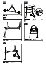
Page 4: ...4 Fig 3 Fig 4 2 M8 70 Fig 5 2 M8 70 Fig 6 Fig 7 2 M8 65 1 42 2 M8 20 ...
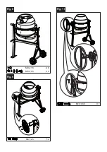
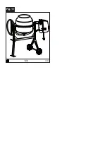
Page 5: ...Fig 8 Fig 9 Fig 10 F 2 M8 20 6 M8 16 2 M8 25 1 M10 65 ...
Page 6: ...Fig 11 4 M8 ...
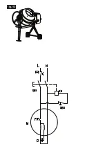
Page 8: ...WIRING DIAGRAM Fig 13 ...
Page 31: ......
Page 33: ......
Page 34: ......

