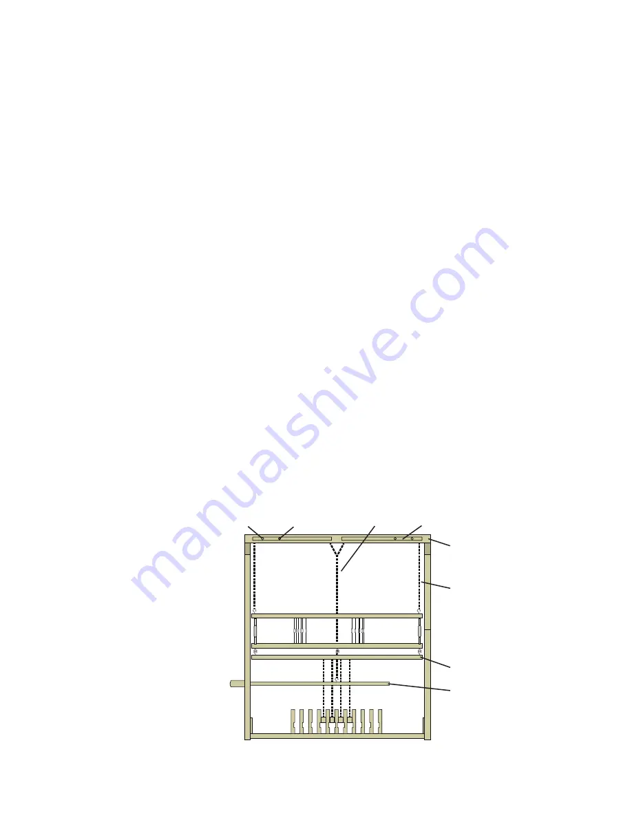
INSTALL THE TREADLES ON THE TREADLE
SUPPORT BAR
Parts: treadle support bar.
Make sure the flat sides of the treadles face up. Remove both
cotter pins and wooden washers from the treadle support bar.
Slide the steel rod out to one side of the three support blocks
(see Figure 2, page 5). It is easiest to install the treadle in its
corresponding slot on the treadle separator beam as you place
the treadles on the treadle support bar.
The support bar accommodates six treadles (including one
treadle installed outside of the support block) on each side of
the center support block. For fewer than 12 treadles, place an
equal number of treadles on either side of the center support
block and use the additional spacers provided to fill any
leftover space.
Working out from the center support block to one side, install
half the treadles included with your loom. Slide a treadle onto
the support bar, and then a 1-1/2" wooden spacer, treadle,
spacer, etc. Then install the remaining treadles on the other
side of the support bar, again working out from the center.
When all treadles and/or spacers have been installed, secure
both ends of the treadle bar with a wood washer and a cotter
pin.
ATTACH THE LOWER LAMM ASSEMBLY
Parts: lower lamm assembly.
Leave the wrapping materials in place until you have attached
the lamms. Make sure the hooks on the lower lamms face
up. From the inside of the left frame side, insert 3/8" x 3-1/2"
hex bolts and 3/8" washers into the two holes for the lower
lamm assembly (see Figure 2, page 5). Insert a barrel nut into
each extension block. Slide the extension blocks over the hex
bolts, turning the barrel nuts if needed. Tighten the hex bolts
securely.
INSTALL THE STEEL BEAMS
Parts: 3 steel beams. The breast and knee beams attach with
truss head bolts; the back beam attaches with hex bolts.
Breast Beam: The breast beam fits into the slots at the top of
the front uprights (see Figure 1, page 4). Thread a 1/2" flat
washer and then a 1/2" fender washer onto each of two 3"
truss head bolts. Insert the bolts into both ends of the beam
and turn the bolts about 1/2" deep into the fittings. Position
the beam with the bolts over the slots in the front uprights,
with the fender washers on the inside and the flat washers on
the outside of the frame. Slide the beam down to the bottom
of the slots. Tighten the bolts by hand, then use the Allen
wrench to secure as tightly as possible.
Back Beam: The back beam fits in the fourth hole from the
top in the rear uprights of the side frames. (Holes closer to the
top accept an optional double back beam and optional tension
box rail.) Attach one end of the back beam at a time. Thread
a 1/2" flat washer onto a 3" hex bolt, then from the outside of
the loom, insert the hex bolt partway into its hole. From inside
the loom, slide a 1/2" fender washer onto the bolt. Raise the
back beam into position and hand tighten the hex bolt into the
beam. Repeat on the other side of the loom.
Knee Beam: The steel knee beam allows for additional leg
room within the loom. Woven material passes over the top of
the knee beam to the cloth beam below. Install the knee beam
in the same way as the back beam, using two 3" truss head
bolts, two 1/2" washers outside of the rear uprights, and two
1/2" fender washers inside of the uprights.
Once the back and knee beams are installed, tighten all beam
bolts with the Allen wrench. Tap all six wedges for the three
wooden cross beams firmly into place again.
INSTALL THE JACK BOX
Parts: jack box.
Set the jack box on the top of the loom, lining up the pegs in
the bottom of the jack box with the holes on the top of the
frame sides (see Figure 2, page 5). The wooden knobs of the
jack pivots and locking pins should face the front of the loom,
and the cords should hang down (Figure 6). Take care that
the locking pins do not fall out as you maneuver the jack box
into place.
— 8 —
FIGURE 6: JACK AND LAMM ASSEMBLY
— 8 —
lower lamms
upper (suspended) lamms
shaft suspension cord
jack box
jacks (inside jack box)
yoke cord
jack lock
jack pivot


