


4
can be taken off. The new grinding wheel is not allowed to exceed the measures given on the motor sign
on the machine. It is very important that the hole dimension is correct. The grinding wheels are supplied
with labels (discs made of pressed material), which are placed around the holes on both sides of the
grinding wheel. If these labels are damaged or missing they must be replaced by new ones of the same
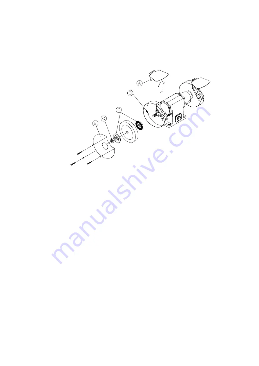
dimension. The new grinding wheel is mounted between the two flanges (D) and the lock nut (C) is
screwed on and tightened. The lock nut (C) must be tightened enough to hold tight the grinding wheel but
not too tight as this will result in unwanted tension in the grinding heel.
Fig.: 2.1
3 Trimming
3.1 Assembling and mounting of trimming attachment/deburring
The deburring cover is assembled as shown in
fig.: 3.1.
The four screws in the end cover (A) is
unscrewed and the mounting plate (B) is placed on the end cover (A). The four counter sunk machine
screws M6x20 (C) are screwed in. Now the deburring cover (D) can be mounted during the two slits in
the mounting plate (B), the cover can be moved back and forth so that the steel brush (G) can be utilized
better. The inner flange (F) is mounted on the shaft together with the steel brush (G) and the outer flange
(H). Last the lock nut (I) is screwed onto the shaft and tightened. Before the lid for the deburring cover
(D) is closed, the eye shield (J) is mounted (as shown in
fig.: 3.1
.). If you are not going to trim a pipe you
can dismount the tool rest for pipe trimming (K) and use the flat tool rest below the other one.
Summary of Contents for SC 250 T
Page 16: ...14 5 5...


