background image

Installing the Nexus N-3030

13

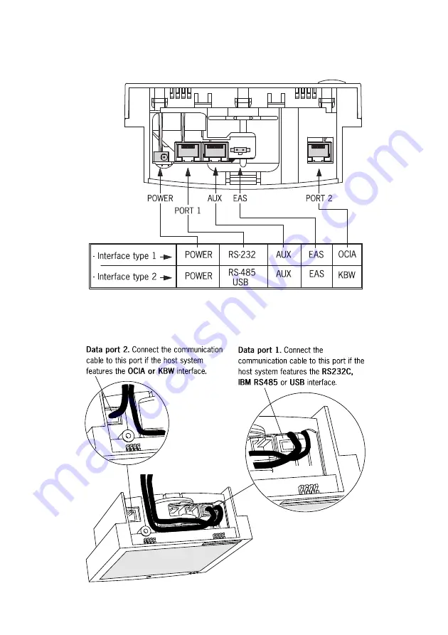
Use the illustration below to see where to connect your cable(s) to the scanner.

Check whether you have to use Port 1 or Port 2 for your type of data-interface.

Before closing the end cover later on (see mounting instructions in chapter 2.2

and 2.3) guide the cables through the scanner as shown in the illustration below.

Summary of Contents for Nexus N-3030

Page 1: ...u s e r s m a n u a l Scantech Nexus N 3030 Bar code laser scanner ...

Page 2: ......

Page 3: ...User s Manual Scantech Nexus N 3030 ...

Page 4: ...in accordance with the user s manual may cause harmful interference to radio communications Operation of the equipment in a residential area is likely to cause harmful interference in which case the user will be required to correct the interference at his own expense Any unauthorized changes or modifications to this equipment could void the user s authority to operate this equipment For CE countri...

Page 5: ...canner 8 1 5 Controlling the scanner from the POS system 9 2 1 Connecting the scanner 12 2 2 Installing the scanner on a counter surface 14 2 3 Installing the scanner using the flexible scanner stand 16 2 4 Removing the scanner from the end cover 20 Appendices 21 A Connector types and pin definitions 22 B Technical specifications 25 C Troubleshooting 27 ...

Page 6: ......

Page 7: ...tically The scanner can be re activated by pressing the switch on top of the scanner The Nexus N 3030 is available in two versions Each version features a specific multiple interface for communication with the host system The multiple interface versions are RS232C OCIA and IBM RS485 Keyboard Wedge USB versions This manual contains two chapters and three appendices The first chapter describes the N...

Page 8: ......

Page 9: ...Chapter 1 The Nexus N 3030 ...

Page 10: ...ems ordered Visually inspect the scanner and accessories for any evidence of physical damage Refer to the upper figure on page 5 to locate the interface label and make sure that the scanner interface corresponds with the host system interface Immediately contact your supplier if anything appears to be damaged or if the supported interface does not correspond with the host system interface ...

Page 11: ... read buzzer The buzzer is heard whenever data has been read correctly The frequency and volume can be adjusted Optional parts accessories Flexible scanner stand The rotary and flexible stand allows you to direct the scan pattern in a way that is optimal for your application a mounting kit with screws and tapes is included End cover This part serves to fix the scanner to the counter or to the stan...

Page 12: ...me is illustrated in the figure below The optimal reading zone lies between 2 and 15 cm from the scanner window but bar codes can be read up to 30 cm 11 8 in from the scanner window If a scanner with flexible stand is purchased the stand allows you to direct the optimal reading zone in a way that suits your application most Scanning a bar code label with a presentation scanner is very simple prese...

Page 13: ...wo labels are also visible through the scanner window All labels are attached by the manufacturer and should not be removed Scantech ID BV Amersfoortsestr 124 3769 AN Soesterberg Netherlands The scanner s serial number is found underneath the bar code label as depicted in the figure above This official registration number is strictly related to the device The supplier may ask for this number when ...

Page 14: ...ys i længere perioder Finnish N 3030 skanneri täyttää luokan I lasertuotteelle IEC 825 1 ssä 1993 asetetut turvavaatimukset Se täyttää myös U S 21CFR1040 ssa asetetut vaatimukset siltä osin kuin ne koskevat luokan IIa lasertuotetta Vältä pitkäaikaista suoraan laservaloon katsomista Swedish Avsökaren N 3030 uppfyller säkerhetsnormen IEC 825 1 1993 för laserprodukter av klass 1 Den uppfyller dessuto...

Page 15: ...ight observed at 13 cm 5 1 in above the window through a 7 mm 0 28 in aperture and averaged over 1000 seconds is less than 3 9 µW per CDRH Class IIa specification Do not attempt to remove the protective housing of the scanner as unscanned laser light with a peak output up to 0 8 mW could be accessible inside Laser Light Viewer The scanner window is the only aperture through which laser light may b...

Page 16: ... Nexus N 3030 scanner requires little maintenance Only occasional cleaning of the scanner window is necessary to remove dirt and fingerprints Cleaning can be performed during operation with a non abrasive glass spray cleaner and a soft lint free cloth ...

Page 17: ... the Scantech default setting the following commands are available more details upon request ASCII code Function byte is also called 05 Hex power up re initialization ENQ or Ctrl E OE Hex enable cancels disable Shift Out or Ctrl N OF Hex Disable Shift In or Ctrl O 12 Hex sleep DC2 or Ctrl R 14 Hex wake cancels sleep DC4 or Ctrl T When the scanner is disabled the motor of the scanner will stay on u...

Page 18: ......

Page 19: ...Chapter 2 Installing the Nexus N 3030 ...

Page 20: ...st be switched off before starting the installation of the scanner By following this precaution you prevent any electrical damage You are advised to install the scanner in an air circulated place out of direct sunlight 2 1 CONNECTING THE SCANNER Before you connect any cables to the scanner check whether you should guide them through the foot or counter surface The Nexus N 3030 is available in two ...

Page 21: ... connect your cable s to the scanner Check whether you have to use Port 1 or Port 2 for your type of data interface Before closing the end cover later on see mounting instructions in chapter 2 2 and 2 3 guide the cables through the scanner as shown in the illustration below ...

Page 22: ...ithout the flexible scanner stand follow the instructions below 1 Remove the two rubber feet from the end cover Lead the communication cable and power supply cable through the slit Fasten the end cover to the surface with two screws as illustrated in the figure NOTE You can use the end cover as a template to mark the places for the mounting holes at the counter surface and drill two holes If you d...

Page 23: ...e using an external power supply power on the scanner by connecting the IEC power cord to the AC DC power supply and plugging the AC power cord into an AC power outlet Switch on the host system IMPORTANT To activate Data port 2 OCIA or KBW interface scan the following codes from the Configuration Guide 1 open the scanner Programming Mode by scanning code 1 1 2 return to factory default settings by...

Page 24: ...the bottom plate from the stand 2 Place the bottom plate on the counter and mark the places for the mounting holes on the counter top and mark the hole to lead the cables through 3 Drill the mounting holes and the lead through hole NOTE If you prefer not to drill in your counter you can mount the stand using the provided double sided tape and have the cables leave the foot at the rear just above t...

Page 25: ...ner Refer for the data cable in particular to chapter 2 1 for the correct connections 8 Place the scanner onto the flexible stand and rotate the scanner as indicated in the figure Make sure that connectors and cables are properly placed to allow easy attachment Press the scanner until a click is heard ...

Page 26: ...le In case you have an external power supply connect the IEC power cord to the AC DC power supply and plug the AC power cord into an AC power outlet 12 Switch on the host system IMPORTANT To activate Data port 2 OCIA or KBW interface scan the following codes from the Configuration Guide 1 open the scanner Programming Mode by scanning code 1 1 2 return to factory default settings by scanning code 1...

Page 27: ...g the Nexus N 3030 19 Once the scanner is installed you can start scanning bar code labels If you want to change the default settings of the scanner proceed to the Configuration Guide which came with the scanner ...

Page 28: ...THE END COVER To remove the scanner from the end cover that is either attached on the counter or on the scanner stand 1 Locate the small hole at the end cover of the scanner 2 Remove the end cover by pressing it with the tip of a stick as indicated in the figure ...

Page 29: ...Appendices A Connector types and pin definitions B Technical Specifications C Troubleshooting ...

Page 30: ...Data port are given on page 20 and 21 The connector to be used for the port is indicated below IMPORTANT To activate Data port 2 OCIA or KBW interface follow this sequence 1 Plug in the appropriate interface cable and then power up the scanner 2 Scan the following codes from the Configuration Guide Open the scanner Programming Mode by scanning code 1 1 Return to factory default settings by scannin...

Page 31: ...t reserved 8 RESET RTN input Note Connect pin 1 to 3 Pin definition for triple interface version RS485 KBW USB RS485 interface Data port 1 USB interface Data port 1 Pin Description Direction Pin Description Direction 1 Do not connect 1 D input output 2 IO A input output 2 Do not connect 3 IO B input output 3 Do not connect 4 Do not connect 4 D input output 5 GND 5 GND 6 DC POWER input 6 DC POWER I...

Page 32: ...6 PC CLK input 7 PC 5V input 8 IFID 2 input Note connect pin 1 to 8 Pin definition for all scanner versions AUX Port Aux EAS Pin Description Direction Pin Description Direction 1 5 VDC output 1 2 CTS input 2 3 RXD input 4 reserved 5 RTS output POWER 6 GND Pin Description Direction 7 reserved 1 GND 8 reserved 2 input 9 reserved 10 reserved ...

Page 33: ...tical Light source Visible laser diode 630 670 nm Depth of field 300 mm Scan pattern 7 directions scan field 24 lines scan pattern Scan rate 2480 scans second Decoding Bar code types EAN UPC JAN Add on code 32 Ital Pharmacode Code 128 EAN 128 Code 39 full ASCII Codabar Interleaved 2 5 Physical Weight 500 g Weight with stand 675 g Dimensions H x W x D 146 x 135 x 61 mm 5 75 x 5 35 x 2 40 inch Dimen...

Page 34: ...DRH 21CFR1040 Class II a Electrical safety EN 60950 second edition UL1950 c UL according CSA22 2 950 Flammability rate 94V 0 EM Compatibility Radio and TV interference EN 55022 Class B 1998 A1 2000 FCC part 15 Class A 1992 Harmonic current emissions EN 61000 3 2 1995 A1 1998 A2 1998 EM immunity EMC Directive 89 336 EEC EN 55024 1998 A1 2001 ...

Page 35: ... disabled by the host Refer to Section 1 5 The bar code type you presented to the scanner is not supported by the Nexus The scanner is on but the motor is not rotating A bar code cannot be read The LED is intermittently flashing red The scanner is in sleep mode Press the switch on top of the scanner to reactivate the scanner or use the wake protocol Refer to section 1 5 The LED is alternating red ...

Page 36: ...he scanner and the host Scanner buffer is full Make sure that all cables are connected and your host system is ready to receive data A bar code is read by the scanner but not accepted by the host system The communication cable is not connected to the serial port of your host system Refer to the manual of your host system to locate the serial port The communication settings of the host and scanner ...

Page 37: ...t install some general drivers possibly from your computer setup CD In case of KB emulation you can select various keyboard languages or the universal Alt input method In a windows environment verify with the device manager that a HID Human Interface Device is installed for the scanner Check that scanner and POS system or Computer both expect the same USB protocol KB emulation RS 232 emulation or ...

Page 38: ......

Page 39: ......

Page 40: ...Scantech ID BV Amersfoortsestraat 124 3769 AN Soesterberg The Netherlands Phone 31 0 33 469 84 00 Fax 31 0 33 465 06 15 E mail info scantech id com Internet www scantech id com ...

Reviews: