background image

SPECIFICATIONS 


USER’S MANUAL 

SWEEP

 V1.0 


Copyright ©2014-2017 Scanse LLC - www.scanse.io 

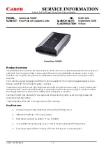
The status LED (Light Emitting Diode) located on the 
base of the sensor can give valuable feedback. 
 

Display 

Meaning 

Blinking 
Green 

Initial startup routine.  
No data is output at this time. 

Solid Blue  Normal operation. 
Solid Red  Internal communication error. 


Figure 7, Status LED Location

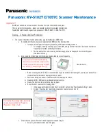
Sweep has four brass threaded inserts designed to fit 
M2.5X0.45 screws in its base. These threaded holes 
are the way to mount Sweep to your device. The 
threaded 

holes are aligned with the scanner’s 

measurement angles. 

The scanner’s 

zero-degree 

measurement starting angle is aligned with the 
status LED, as shown in 
Figure 8. 

Sweep can be mounted in any orientation. Sweep’s 

rotating head is dynamically balanced, which means 
it is immune to linear vibration, but it can be 
affected by rotational vibration. Sudden rotational 
shocks can cause the head to either slow down or 
speed up, which can affect angular measurements. If 
Sweep is rotationally jerked hard enough, it can 
cause the motor to lose sync, which will trigger a 
momentary motor pause, and then restart. 

If space is limited, the scanner

s plastic bottom piece 

can be removed, and the internal motor mounting 
holes can be used to mount the device instead, as 
shown in Figure 9. Room must be provided for 
airflow around the scanner

s head, and care must be 

taken not to damage the delicate circuit board 
components. Using the scanner in this configuration 
should only be considered by professionals. A 3D 
model that makes these mounting dimensions clear 
can be found on our downloads page. 
 

Sweep is rated as IP51, which is to say, it is not dust 
or water tight. 

It is recommended that Sweep be 

placed inside a protective transparent enclosure if 
it will be used in dusty or wet environments. 


Figure 8, Sweep Standard Mounting Features 


Figure 9, Sweep Internal Mounting Features 

ALL DIMENSIONS ARE IN MM, DRAWINGS ARE NOT TO SCALE 


Summary of Contents for Sweep V1

Page 1: ...cal drawings 0 9 12 19 2016 Initial Release Laser Safety 0 Power Safety 0 Specifications 2 Physical 2 Electrical 2 Measurement Performance 2 Field of View 2 Measurement Error Test Data 2 Overview of I...

Page 2: ...see Theory of Operation Sweep is a single plane scanner This means that as its head rotates counterclockwise it records data in a single plane The beam starts out at approximately 12 7mm in diameter a...

Page 3: ...e internal pull up Pull down to put device in sleep mode 3 Yellow Sync Device Ready Goes high when first range measurement of new scan is completed then goes low when second range measurement is compl...

Page 4: ...Sudden rotational shocks can cause the head to either slow down or speed up which can affect angular measurements If Sweep is rotationally jerked hard enough it can cause the motor to lose sync which...

Page 5: ...e Under normal operation Sweep limits the maximum time per measurement to a value determined by the sample rate set using the LR command see LR packet structure description If not enough light is retu...

Page 6: ...with ASCII letter command codes HOST SENSOR Command with no parameter Command Symbol 2 bytes Line Feed 1 byte Example DS DX MI IV Line Feed LF or Carriage Return CR or Command with parameter Command...

Page 7: ...al processing of a command ASCII byte values of 00 or 99 indicate that the sensor received and processed the command normally Value of 11 specifies an invalid parameter was included in the command Any...

Page 8: ...ation about a single sensor reading Sync Error Byte The sync error byte is multi purpose and encodes information about the rotation of the Sweep sensor as well as any error information Consider the in...

Page 9: ...e measurements This calibration routine is initiated after powering on the device after receiving any form of Adjust Motor Speed MS command regardless of the size of the adjustment ie even calling MS...

Page 10: ...z 08 8Hz 09 9Hz 10 10Hz MS command is not guaranteed to succeed There are a few conditions where it will fail In the event of a failure the two status bytes are used to communicate the failure Status...

Page 11: ...Hz LR command is not guaranteed to succeed There are a few conditions where it will fail In the event of a failure the two status bytes are used to communicate the failure Status Code 2 byte ASCII cod...

Page 12: ...LF Example IVSWEEP01011100000001 I V SWEEP 01 01 1 00000001 LF Returns details about the device s current state settings Bit Rate Laser State Mode Diagnostic Motor Speed Sample Rate HOST SENSOR I D L...

Page 13: ...s 0x30 return sum checkSumByteValue Example Consider the common case of 00P decimal 48 48 80 hex 0x30 0x30 0x50 0x30 0x30 0x60 sum of the status bytes 0x60 0x3F 0x20 retrieve only the lower 6 bits 0x2...

Page 14: ...e sum of 6 other bytes Instead the checksum byte uses the modulo operation and effectively contains the remainder after dividing the sum by 255 this is the same as saying sum 255 Validating the checks...

Reviews: