23
SCAIME Manual : NU-eNod4C-E-0418-196712-F.docx
5
COMMUNICATION
5.1
Communication Interface connections
5.1.1
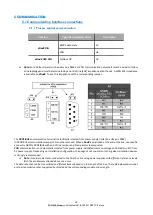
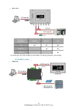
Process control communication
Version
Type of communication
Connector
eNod4 DIN
RS485 Automate
A7
CAN
A6
eNod4 PRO DIN
Profibus DP
A7
Note:
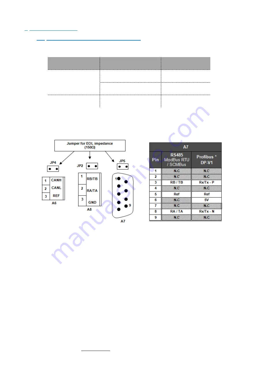
For a better transmission quality on a RS485 or CAN communication network it must be wired to follow
a line topology and must be terminated by an end of line (EOL) impedance at both ends.
A 150Ω EOL
impedance
is available on
eNod4
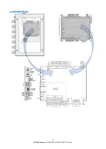
. To use this impedance set the corresponding jumper.
The
PROFIBUS
communication terminal is electrically isolated from power supply (isolation voltage: 1000V)
In PROFIBUS communication jumper JP5 must be removed. When
e
Nod4
is positioned at the end of the line, use specific
connector DB9 for PROFIBUS with end of line resistor and bias resistors incorporated.
CAN
communication is not electrically isolated from power supply. Admitted common voltage on CANBUS is
27V from
0V power supply. Depending on installation configuration, the usage of opt couplers or other galvanic isolation devices
is strongly recommended.
Note
: If multiple elements connected to the CAN bus are using power supplies with different reference levels
(0V); the problem mentioned above can occur.
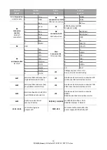
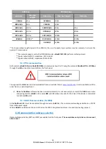
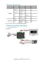
The data rate that can be transmitted on different buses depends on the length of the bus. The table below shows what
are the transmission rates supported by
e
Nod4 and the corresponding maximum bus length:

