background image

13

Section 4

R

10.  Collecting debris into piles for the machine to 

intercept prior to start up will save time and fuel as 
well as wear and tear on the unit.

11.  Keep the truck loader's intake nozzle and discharge 

clean.

12.  Use a slow travel speed when clearing heavy or 

large amounts of material.

4.6 HILLSIDE OPERATION

Slopes are a major factor related to loss-of-control and tip 
over accidents which can result in severe injury or death. 
All slopes require extra caution.

 WARNING

DO NOT operate on steep slopes. Poor footing 
could cause a slip and fall accident. ALWAYS 
FOLLOW OSHA APPROVED OPERATION.

1.  Do not operate on slopes if you are uneasy or 

uncertain. Ultimate responsibility for safe operation 
on slopes rests with the operator.

2.  Be sure of footing on slopes.

3.  Caution must be used when operating on slopes, 

especially when the grass is wet. Wet grass reduces 
traction and control.

4.  To prevent tipping or loss of control, keep all 

movements on slopes slow and gradual.

5.  Do not turn on slopes unless necessary, and then 

turn slowly and down hill when possible.

6.  Do not start or stop on slopes. If tires lose traction, 

stop the unit and proceed slowly straight down the 
slope.

7.  Be alert for holes, rocks, roots, ruts and other hidden 

hazards in the terrain. Uneven terrain could cause a 
slip and fall accident.

8.  Do not operate near drop-offs, ditches, or 

embankments. The operator could lose footing or 
balance or unit could suddenly turn over if a wheel is 
over the edge of a cliff or ditch, or if the edge caves 
in.

4.7 UNCOUPLING THE UNIT FROM THE TOW 
VEHICLE

1.  Park the machine on a flat, level surface only. Do not 

park the machine on an incline.

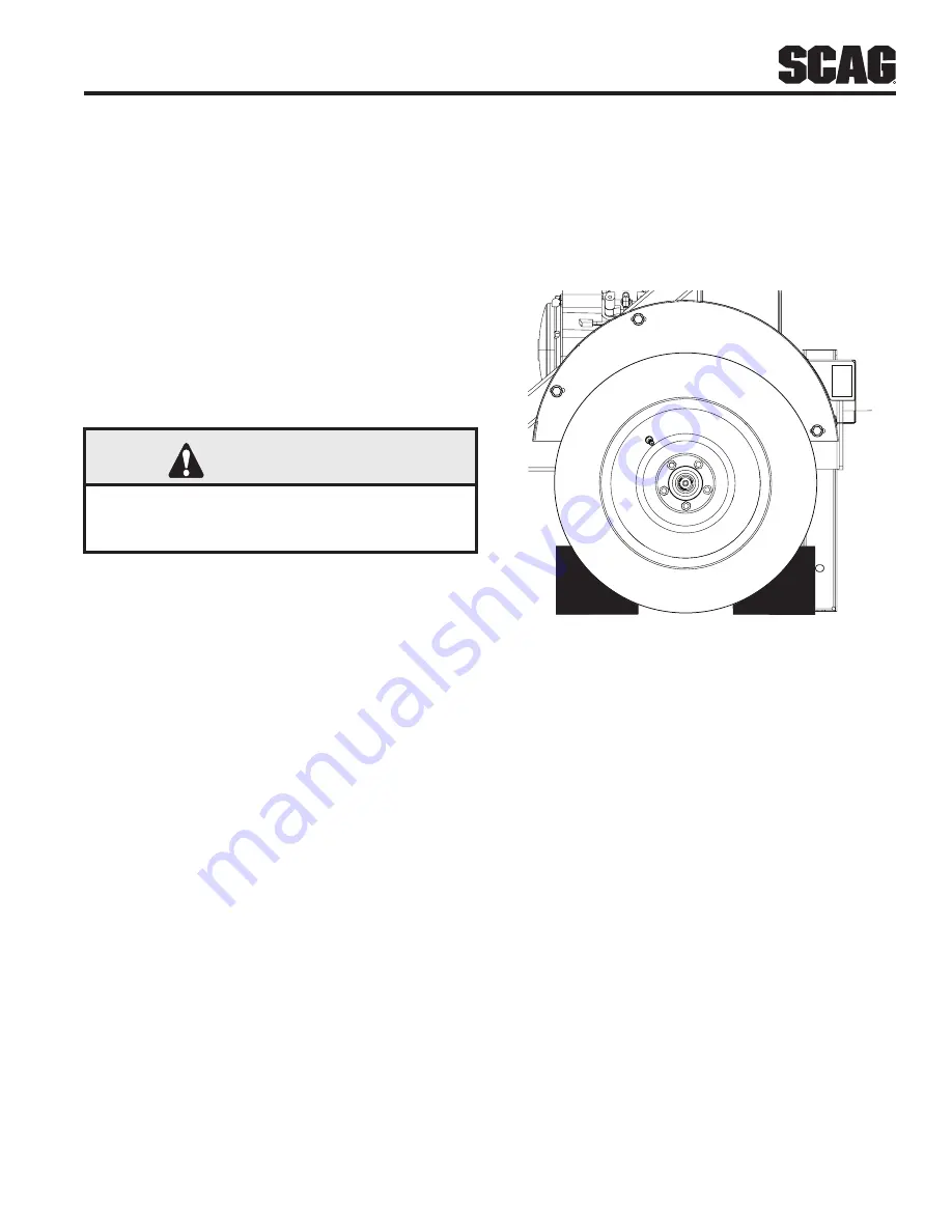
2.  Block the wheels to prevent the machine from 

moving. See Figure 4-4.

Figure 4-4. Wheel Chocks

3.  Disconnect the trailer wiring plug from the tow 

vehicle.

4.  Unhook the safety chains from the rear of the tow 

vehicle.

5.  Unlock the ball hitch coupler lever on the unit and flip 

up.

6.  Crank down the tongue jack until the ball hitch 

coupler on the unit clears the ball hitch on the tow 
vehicle.

7.  Pull and turn the spring latch to unlock the pin 

securing the rear support leg in the transport 
position. See Figure 4-5.

Summary of Contents for TLB25-35BV Series

Page 1: ...ormation for your Scag truck loader Reading this manual can provide you with assistance in maintenance and adjustment procedures to keep your truck loader performing to maximum efficiency The specific...

Page 2: ...all safety features are attached adjusted and functioning properly Before performing any maintenance or service stop the machine and remove the spark plug wire If a mechanism becomes clogged stop the...

Page 3: ...ION 3 SPECIFICATIONS 8 3 1 ENGINE 8 3 2 IMPELLER 8 3 3 WEIGHTS AND DIMENSIONS 8 SECTION 4 OPERATING INSTRUCTIONS 10 4 1 CONTROLS AND INSTRUMENT IDENTIFICATION 10 4 2 INITIAL RUN IN PROCEDURES 11 4 3 C...

Page 4: ...ED ATTACHMENTS AND ACCESSORIES 20 INTAKE AND DISCHARGE ASSEMBLY 22 IMPELLER HOUSING ASSEMBLY 24 IMPELLER DRIVE ASSEMBLY 26 TRAILER ASSEMBLY 28 FUEL AND ELECTRICAL SYSTEM 30 TLB25 TRUCK LOADER DECALS 3...

Page 5: ...s and accessories manufactured by companies other than Scag Power Equipment are not approved for use on this machine See Section 6 1 GENERAL INFORMATION WARNING For pictorial clarity some illustration...

Page 6: ...CRIPTION SYMBOL DESCRIPTION Choke Transmission On Start Spring Tension on Idler Off Stop Oil Spinning Fan Blades Thrown Object Hazard Fast Slow Continuously Variable Linear Pinch Point Keep Bystanders...

Page 7: ...y and possible death carefully read the message Be sure to fully understand the causes of possible injury or death SIGNAL WORD It is a distinctive word found on the safety decals on the machine and th...

Page 8: ...accessories and attachments are needed to properly and safely perform the job Use only approved attachments and accessories 13 See Section 5 3 ENGINE FUEL SYSTEM for fueling procedure 14 Use a funnel...

Page 9: ...ting to start the engine inspect the machine inlet hose discharge debris receiver box shields and safety devices for any damage Correct any problems before operating 13 Stop on level ground and shut o...

Page 10: ...gine free of grass leaves excessive grease oil and dirt 8 Park the machine on level ground 9 Block the wheels to prevent the machine from moving 10 Lower the Support Leg to the ground and secure with...

Page 11: ...veral minutes Remove cap slowly Do not overfill 484281 484281 WARNING Operation of this equipment may create sparks that can start fires around dry vegetation A spark arrestor may be required The oper...

Page 12: ...00 Fixed Jet Briggs Stratton Fixed Jet Fuel Pump Kohler Mechanical with In Line Fuel Filter Briggs Stratton Mechanical with In Line Fuel Filter Fuel Non Leaded Gasoline with a Minimum Octane Rating of...

Page 13: ...9 Section 3 R...

Page 14: ...ottle Control Figure 4 1 Used to control the engine speed Pushing the lever inboard increases engine speed Pulling the lever outboard decreases engine speed Full outboard position is the IDLE position...

Page 15: ...ll coupler on the truck loader is approximately 3 4 inches higher than the ball hitch on the tow vehicle Flip the lock lever up on the ball hitch coupler 3 With assistance behind back up slowly align...

Page 16: ...otection when operating machine 1 Read Section 2 3 BEFORE OPERATION CONSIDERATIONS and Section 2 4 OPERATION CONSIDERATIONS before operating CAUTION Tow at speeds appropriate for conditions Reduce spe...

Page 17: ...o not turn on slopes unless necessary and then turn slowly and down hill when possible 6 Do not start or stop on slopes If tires lose traction stop the unit and proceed slowly straight down the slope...

Page 18: ...hicle away 4 8 AFTER OPERATION 1 When machine is not in operation in storage or transporting lock the hose support boom and secure hose on the storage pin Pull and turn the spring latch to lock the pi...

Page 19: ...essary 4 9 REMOVING CLOGGED MATERIAL DANGER ROTATING FAN BLADES NEVER PUT YOUR HANDS INTO THE VACUUM INTAKE OR DISCHARGE FOR ANY REASON Shut off the engine remove the spark plug wire and only then use...

Page 20: ...5 X Change engine oil and filter See engine operator s manual X Clean air filter element See engine operator s manual X Grease Impeller Shaft Bearings See Below X Check condition of fuel lines X Chec...

Page 21: ...E OIL LEVEL The engine oil level should be checked after every 8 hours of operation or daily as instructed in the Engine Operator s Manual furnished with this truck loader B CHANGING ENGINE CRANKCASE...

Page 22: ...to allow the engine to move 6 Using a belt tension gauge adjust the impeller drive belt tension by turning the adjustment studs on the right side of the engine an equal amount of turns 7 Adjust to ac...

Page 23: ...ase fittings located on the left side of the machine every 50 hours or weekly whichever comes first of operation See Figure 5 3 GREASE FITTINGS Figure 5 3 Impeller Shaft Grease Fittings 5 7 WHEELS TIR...

Page 24: ...ttachments and accessories manufactured by companies other than Scag Power Equipment are not approved for use on this machine Scag Power Equipment approved attachments and accessories Truck Loader Lig...

Page 25: ...21 R Section 6 NOTES...

Page 26: ...22 Section 6 R A A A 1 2 3 4 5 6 11 5 7 8 10 9 12 13 15 14 16 19 17 21 22 18 20 23 24 26 27 2 25 28 29 30 2 21 INTAKE AND DISCHARGE ASSEMBLY...

Page 27: ...Head 1 2 13 x 1 1 2 Flatwasher 1 2 562 x 1 375 x 109 Bracket License Plate Nut Elastic Stop 1 2 13 Nut Elastic Stop 1 4 20 Bolt Hex Head 1 4 20 x 4 Stack Assembly w Decals Disk Anti Friction Boom Weld...

Page 28: ...24 Section 6 R 1 2 2 3 4 10 11 6 7 8 9 12 7 6 3 5 IMPELLER HOUSING ASSEMBLY...

Page 29: ...05 Base and Frame w Decals Bolt Hex Head 7 16 14 x 3 4 Nut Serrated Flange 7 16 14 Bolt Serrated Flange 3 8 16 x 3 4 Impeller Housing Assembly TLB25 incl 6 7 8 9 12 Flatwasher 1 2 561 x 1 375 x 109 Nu...

Page 30: ...1 12 14 13 14 11 12 15 16 17 21 21 21 21 22 23 20 18 18 18 18 19 2 24 2 25 2 26 27 32 32 30 29 31 28 33 34 35 32 35 36 28 28 32 26 27 34 33 34 35 35 37 2 3 4 2 23 39 40 41 2 42 G G 43 44 45 46 47 48 4...

Page 31: ...g 45 Degree 1 4 28 x 813 Shaft Impeller TLB25 Key 3 8 x 3 8 x 2 1 4 Pulley Sheave 3v6 9 x 5 SK Bushing Taper SK 1 7 16 incl hardware Belt R3V x 450 5 Key 3 8 x 3 8 x 1 1 4 Hub Taper SDS 1 7 16 incl ha...

Page 32: ...28 Section 6 R TRAILER ASSEMBLY 1 1 33 5 7 2 3 3 4 5 32 30 31 6 7 8 9 10 29 9 4 12 8 11 10 13 8 14 15 16 19 17 18 20 21 22 15 23 23 15 22 24 25 15 16 26 9 27 28 34...

Page 33: ...9 Nut Lock Elastic Stop M12 x 1 Safety Chain Nut Serrated Flange 3 8 16 Bolt Serrated Flange 3 8 16 x 3 4 Chock Box Bolt Hex Head 5 8 11 x 5 1 2 Flatwasher 5 8 688 x 1 750 x 134 Base and Frame w Decal...

Page 34: ...To Engine Vapor Port 1 1 1 1 2 3 19 31 29 4 5 6 1 1 8 39 7 7 9 6 8 40 25 27 26 10 11 12 13 14 11 15 13 17 18 16 17 18 16 19 13 15 11 13 12 11 20 21 11 22 23 24 23 28 34 41 34 35 23 22 38 37 36 37 33...

Page 35: ...Carriage 1 4 20 x 7 1 2 Pigtail Side Marker Light Side Marker Light Yellow does not include 42 Screw 8 18 x 3 4 Self Tap Nut Serrated Flange 3 8 16 Side Marker Light Red does not include 42 Stop Turn...

Page 36: ...ECALS WARNING INSTALL BELT COVER BEFORE OPERATING MACHINE READ OPERATOR S MANUAL 483402 Avoid injury from burns Shut off engine Allow to cool several minutes Remove cap slowly Do not over fill 484281...

Page 37: ...IL LIGHT R H REAR SIDE MARKER LIGHT L H REAR SIDE MARKER LIGHT R H FRONT SIDE MARKER LIGHT L H FRONT SIDE MARKER LIGHT LICENSE PLATE LIGHT TOW VEHICLE CONNECTOR WHITE GREEN YELLOW WHITE BROWN BROWN BR...

Page 38: ...nce or accident or that has been operated in any way contrary to the operating instructions as specified in the Operator s Manual The warranty does not apply to any damage to any truck loader that is...

Reviews: