background image

10

Section 4

OPERATING INSTRUCTIONS

Do not attempt to operate this mower unless you
have read this manual.  Learn the location and
purpose of all controls and instruments before you
operate this mower.

4.1 CONTROLS AND INSTRUMENT
      IDENTIFICATION

Before operating the mower, familiarize yourself with all
mower and engine controls.  Knowing the location,
function and operation of these controls is important for
safe and efficient operation of the mower.

CAUTION:

1. Ignition Switch (Figure 4-1).  The ignition switch

is used to start the engine and has three positions;
OFF, ON, and START.

2. Mower Deck Switch (Figure 4-1).  Used to engage

and disengage the mower drive system.  Pulling up
on the switch will engage the deck drive.  Pushing
down on the  switch will disengage the deck drive.

3. Engine Choke Control (Figure 4-1).  Used to start

a cold engine.

4. Engine Throttle Control (Figure 4-1).  Used to

control the engine speed.  Pushing the lever forward
increases engine speed.  Pulling the lever back
decreases engine speed.  Full back position is the
IDLE position.  Full forward is the cutting position.

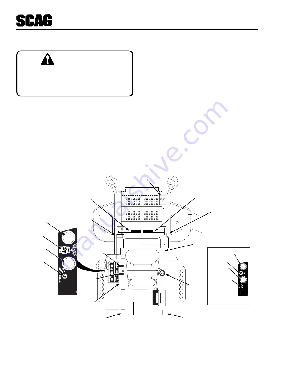
Figure 4-1 Controls and Hour Meter Instruments

CH

O

K

E

48

13

48

F

LEFT STEERING

CONTROL

MOWER DECK

IGNITION SWITCH

FUEL GAUGE

DUMP VALVE

DUMP VALVE

FUSES

ENGINE

CHOKE

CONTROL

ENGINE THROTTLE

CONTROL

RIGHT STEERING

CONTROL

DECK LIFT

DECK RELEASE

390S0142A-1

PARKING BRAKE

CONTROL

CUTTING HEIGHT

ADJUSTMENT

PULL OUT  

T

O

 ENGA

GE

ON

ST

AR

T

PUSH IN 

T

O

 DISENGA

GE

OFF

481669

MO

WER DECK

AMMETER

MOWER DECK SWITCH

IGNITION SWITCH

TEMPERATURE GAUGE

KAWASAKI MACHINE ONLY

AMMETER

SWITCH

WATER TEMPERATURE

Summary of Contents for STT-31BSG

Page 1: ...NTAINS THE OPERATING INSTRUCTIONS AND SAFETY INFORMA TION FOR YOUR SCAG MOWER READING THIS MANUAL CAN PROVIDE YOU WITH ASSISTANCE IN MAINTENANCE AND AD JUSTMENT PROCEDURES TO KEEP YOUR MOWER PERFORMIN...

Page 2: ...nd Instructional Decals 7 Section 3 Specifications 8 9 Section 4 Operating Instructions 4 1 Controls and Instrument Identification 10 4 2 Safety Interlock System 11 4 3 Initial Run In Procedures 12 4...

Page 3: ...gine Fuel System 30 7 6 Engine Air Cleaner 30 7 7 Battery 30 7 8 Drive Belts 32 7 9 Cutter Blades 32 7 10 Tires 33 7 11 Cutter Deck Gearbox 34 7 12 Cooling System 34 7 13 Body Deck Hopper and Upholste...

Page 4: ...s the right to make changes at any time without notice and without incurring any obligation 1 2 DIRECTION REFERENCE The Right and Left Front and Rear of the machine are referenced from the operator s...

Page 5: ...causes of possible injury or death Signal Word It is a distinctive word found on the safety decals on the machine and throughout this manual that alerts the viewer to the existence and relative degre...

Page 6: ...ims to improve operator s view ParkingBrake Lever operated interlocked parking brake prevents operation with parking brake engaged Frame Compact tractor frame with structural steel tubing construction...

Page 7: ...heels 13 x 5 x 6 caster wheels with tapered roller bearing pivots Spindles Heavy duty 1 1 8 top dimension spindle shaft cast housing taper roller bearing low maintenance with top access grease fitting...

Page 8: ...will engage the deck drive Pushing down on the switch will disengage the deck drive 3 Engine Choke Control Figure 4 1 Used to start a cold engine 4 Engine Throttle Control Figure 4 1 Used to control...

Page 9: ...wheel the mower Rotating the levers clockwise until they stop allows the unit to move under hydraulic power The levers must be in this position during operation of the mower Rotating the levers counte...

Page 10: ...for more than 15 seconds at a time Allow at least 60 seconds between each cranking attempt to prevent overheating of the starter motor Prolonged cranking can damage the starter motor and shorten batt...

Page 11: ...traveling in reverse allow the right steering control lever to move forward The further the control is allowed to move forward the quicker the mower will turn right To stop the reverse travel allow th...

Page 12: ...3 Keep tires properly inflated 4 8 PARKING THE MOWER 1 Place the steering control levers in the neutral position 2 Disengage the cutter blades 3 Slow the engine to idle speed 4 Engage the parking brak...

Page 13: ...2 The discharge chute must not be removed and must be kept in the lowest position to deflect grass clippings and thrown objects downward Direct the side discharge away from sidewalks or streets to min...

Page 14: ...s Cutter Deck Level The cutter deck should be level from side to side for proper cutting performance To check for level be sure that the mower is on a flat level surface the tires are properly inflate...

Page 15: ...he top of the cutter deck See Figure 6 7 Tighten the jam nuts on the control rod Figure 6 7 Cutter Deck Stop 3 Check the cutter deck cutting height by placing the lanyard pin in the 3 position on the...

Page 16: ...ution when checking the hydraulic hoses See paragraph 2 5 X Check coolant level See paragraph 7 12 X Check engine oil level See paragraph 7 4 X Clean mower See paragraph 7 14 X Check condition of blad...

Page 17: ...replace hydraulic oil Use SAE 20W50 Motor Oil X Replace hydraulic oil filter See paragraph 7 3 X Replace cutter deck gearbox lubricant See paragraph 7 1 X Change coolant See paragraph 7 12 7 2 LUBRIC...

Page 18: ...Fitting Points 390S0145 1 GREASE FITTING LUBRICATION Lubricant Interval Lithium MP White Grease 2125 40 Hours Weekly Chassis Grease 100 Hours Bi monthly Chassis Grease 200 Hours Monthly Chassis Grease...

Page 19: ...so be changed if the color of the fluid has become black or milky A black color and or a rancid odor usually indicates possible overheating of the oil and a milky color usually indicates water in the...

Page 20: ...LS STT99CDC 1 21 19 37 42 4 6 14 10 42 5 2 3 35 23 41 25 38 32 34 41 30 27 33 40 41 28 28 24 26 41 40 CUTTER DECK 13 40 39 31 41 40 39 43 9 8 45 20 18 36 16 44 17 41 40 26 11 29 22 40 41 15 22 41 7 1...

Page 21: ...nt 24 04020 09 Nut Hex 5 8 11 25 04012 09 Set Screw 5 16 18 x 1 2 Sq Head 26 04040 09 Flatwasher 5 8 656 x 1 312 x 095 27 04041 14 Flatwasher 1 1 062 x 1 50 x 048 28 48114 04 Grease Fitting 29 04061 0...

Page 22: ...OMPONENTS 2001 STTBSG SMC 1 46 48 47 48 15 50 26 30 25 12 15 19 9 6 1 23 24 A 31 32 33 34 29 33 36 37 40 39 38 41 42 43 55 35 45 15 51 53 27 22 54 49 49 20 52 28 15 14 13 12 11 10 16 17 A 20 56 5 3 4...

Page 23: ...W Race 34 482028 01 Plug 1 4 28 THD Form Ref Part No No Description Common hardware which should be purchased locally All bolts Grade 5 plated all other fasteners zinc plated 35 45936 Extention Weldme...

Page 24: ...9 4 10 16 17 18 19 20 21 22 22 23 24 24 25 25 26 27 27 28 29 30 31 32 33 34 37 38 42 40 41 39 43 43 35 44 44 45 46 47 43 50 51 52 53 43 55 54 43 55 45 57 43 58 35 59 60 61 59 63 64 68 42 40 42 40 35...

Page 25: ...x 938 x 105 37 04063 20 Key 1 4 x 1 4 x 1 00 Ref Part No No Description DECK DRIVE COMPONENTS 38 461079 Idler Arm 39 04001 46 Bolt Hex Head 3 8 16 x 2 25 40 04019 04 Nut Serr Flg 3 8 16 41 48181 Pull...

Page 26: ...S ENGINE BRACKETS TO A A ATTACHES TO FRAME 17 22 21 12 13 15 2 9 1 5 11 10 10 6 7 20 19 14 14 3 18 16 16 8 23 24 25 26 27 28 29 30 31 32 35 26 26 36 37 26 26 37 40 36 26 41 42 43 42 44 45 33 4 2k STTB...

Page 27: ...nd Not Available Through Scag Contact Briggs Stratton 25 04003 12 Bolt Carr 5 16 18 x 75 26 04019 03 Nut Serr Flng 5 16 18 27 04069 02 Pin Rue Cotter 1 2 dia 28 04090 04 Rivet Pop 1 8 x 294 29 481817...

Reviews: