background image

25

R

Section 6

 WARNING

If the pump drive belt fails, steering control will be 
lost which could result in serious injury or death. 
Replace the pump drive belt as needed or every 
400 hours / 2 years, whichever occurs fi rst.

6.5 BELT ALIGNMENT

Belt alignment is important for proper performance of 
your Scag mower. If you experience frequent belt wear 
or breakage, see your authorized Scag service center for 
belt adjustment.

6.6 CUTTER DECK ADJUSTMENTS

Cutter deck level, pitch and height are set at the factory. 
However, if these adjustments should ever need to be 
made, the following procedures will aid in obtaining the 
proper cutter deck adjustment.

- NOTE -

Before proceeding with the cutter deck adjustments, 
be sure that all tires are properly inflated. If any 
of these procedures do not achieve proper cutter 
deck level, pitch or height, please contact your 
authorized Scag dealer.

CUTTER DECK LEVEL

The cutter deck should be level from side-to-side for 
proper cutting performance. To check for level, be sure 
that the mower is on a flat, level surface, the tires are 
properly inflated and the cutter deck is set at the most 
common cutting height that you will use. On the RH side 
of the machine, check the distance from the top of the 
cutter deck to the floor. Next check the distance from the 
top of the cutter deck to the floor on the LH side of the 
machine. Both measurements should be the same. If the 
two measurements are different, the cutter deck level must 
be adjusted as follows:

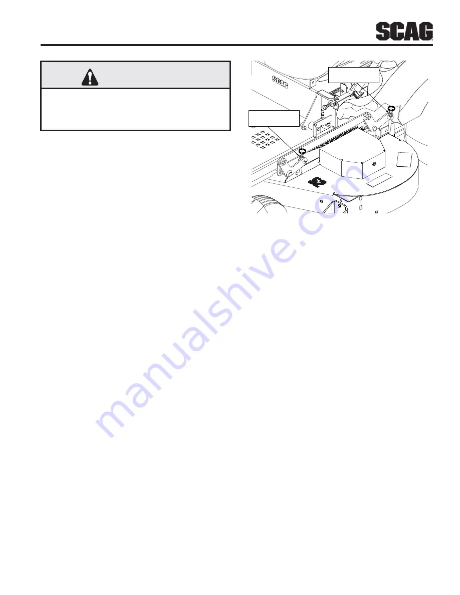
1.  If the cutter deck is lower on one side, locate the 

elastic stop nuts on the front and rear of the lower 
side of the cutter deck. See Figure 6-4.


ADJUSTMENT

NUT

ADJUSTMENT

NUT

Figure 6-4. Cutter Deck Level Adjustment

2.  Turn the elastic stop nuts on the front and rear deck 

level links clockwise until the cutter deck is level 
between both sides. See Figure 6-4

3.  Tighten the two (2) elastic stop nuts to secure the 

cutter deck in the proper position.

CUTTER DECK PITCH

The pitch of the cutter deck should be equal between 
the front and rear of the cutter deck for proper cutting 
performance. To check for proper deck pitch, be sure 
that the mower is on a flat, level surface and the tires are 
properly inflated.

Check the distance from the top of the cutter deck to the 
floor at the rear RH side of the cutter deck directly behind 
the cutter deck hanging link. Next check the distance from 
the top of the cutter deck to the floor at the front RH side of 
the cutter deck directly in front of the cutter deck hanging 
link. The measurement at the front of the cutter deck 
should be the same as the rear of the deck. Make these 
measurements at the LH side of the cutter deck also.  If the 
measurement at the front of the deck is not the same, the 
cutter deck pitch must be adjusted as follows:

1.  Loosen the elastic stop nuts securing the deck level 

links on the front of the cutter deck on both sides. 
See Figure 6-5 and 6-6.

Summary of Contents for Liberty Z SZL36-18FR

Page 1: ...s and safety information for your Scag mower Reading this manual can provide you with assistance in maintenance and adjustment procedures to keep your mower performing to maximum efficiency The specif...

Page 2: ...rge chute Before performing any maintenance or service stop the machine and remove the spark plug wire and ignition key If a mechanism becomes clogged stop the engine before cleaning Keep hands feet a...

Page 3: ...SPARK IGNITION SYSTEM 8 2 12 SAFETY DECAL LOCATION 9 SECTION 3 SPECIFICATIONS 10 3 1 ENGINE 10 3 2 ELECTRICAL 10 3 3 MOWER 10 3 4 CUTTER DECK 11 3 5 HYDRAULIC SYSTEM 11 3 6 WEIGHTS AND DIMENSIONS 11...

Page 4: ...NE FUEL SYSTEM 32 7 6 ENGINE AIR CLEANER 34 7 7 BATTERY 34 7 8 DRIVE BELTS 35 7 9 CUTTER BLADES 35 7 10 TIRES 37 7 11 BODY DECK AND UPHOLSTERY 37 SECTION 8 ILLUSTRATED PARTS LIST 38 8 1 SCAG APPROVED...

Page 5: ...D ATTACHMENTS AND ACCESSORIES Attachments and accessories manufactured by companies other than Scag Power Equipment are not approved for use on this machine See Section 8 Paragraph 8 1 WARNING For pic...

Page 6: ...ning Blade On Start Spring Tension on Idler Off Stop Oil Falling Hazard Thrown Object Hazard Fast Slow Continuously Variable Linear Cutting Element Basic Symbol 481039S Pinch Point Cutting Element Eng...

Page 7: ...on to safety messages found on the decals on the machine and throughout this manual The message that follows the symbol contains important information about safety To avoid injury and possible death c...

Page 8: ...rown by the cutter blades such as rocks wire toys etc 6 DO NOT carry passengers 7 DO NOT operate the machine under the influence of alcohol or drugs 8 If the operator s or mechanic s cannot read Engli...

Page 9: ...inguish all cigarettes cigars pipes and other sources of ignition 6 Keep flammable objects cigarettes matches etc open flames and sparks away from the fuel tank and fuel container 7 Use only approved...

Page 10: ...ng to start the engine with the operator in the seat disengage power to the cutter deck place the steering control levers in the neutral position and engage the parking brake 13 Shut off the engine re...

Page 11: ...r and engine free of grass leaves excessive grease oil and dirt Clean up oil or fuel spillage and remove any fuel soaked debris Allow the machine to cool before storing 7 Park the machine on level gro...

Page 12: ...fler It is in violation of California Public Resource Code Section 4442 to use or operate this engine on or near any forest covered brush covered or grass covered land unless the exhaust system is equ...

Page 13: ...NG WARNING WARNING WARNING DANGER DANGER DANGER DANGER DANGER DANGER WARNING WARNING 483505 483402 483505 483406 483402 483505 molded into tank molded into tank DANGER DANGER 485667 Under Seat 485625...

Page 14: ...e Key Operated Interlock Switches Seat Neutral Control Mower Engagement BBC Parking Brake Instrument Panel Key Switch Throttle Lever Manual Choke PTO Switch Hourmeter Fuses Two 2 20 Amp 3 3 MOWER Driv...

Page 15: ...Black Polypropylene Plastic Flexible Spindles Heavy Duty Spindle Shaft Cast Aluminum Housing Sealed Ball Bearing Maintenance Free Spindle Pulleys Split Steel Cutter Deck Belts B section with Kevlar C...

Page 16: ...F ON and START 2 Mower Deck Switch Figure 4 1 Used to engage and disengage the mower drive system Pulling up on the switch will engage the deck drive Pushing down on the switch will disengage the deck...

Page 17: ...deck 12 Cutting Height Adjustment Figure 4 1 Used to set the cutter deck at the desired cutting height 4 2 SAFETY INTERLOCK SYSTEM The mower is equipped with a safety interlock system that prevents th...

Page 18: ...re if necessary See Section 7 10 4 4 STARTING THE ENGINE CAUTION DO NOT USE STARTING FLUIDS Use of starting fluids in the air intake system may be potentially explosive or cause a runaway engine condi...

Page 19: ...mower will turn right NOTE Smooth operation of the steering levers will produce smooth mower operation While learning the operation of the steering controls keep the travel speed low IMPORTANT Do not...

Page 20: ...Operation on all slopes requires extra caution If you can not back up a slope or feel uneasy do not mow it WARNING DO NOT operate on steep slopes To check a slope attempt to back up it with the cutte...

Page 21: ...angle should be no more than 15 degrees See Figure 2 1 to help determine approximate slope Back up the ramp and drive down forward 4 8 PARKING THE MOWER 1 Park the machine on a flat level surface only...

Page 22: ...ippings and thrown objects downward Direct the side discharge away from sidewalks or streets to minimize cleanup of clippings When mowing close to obstacles direct the discharge away from the obstacle...

Page 23: ...NOT AVAILABLE FOR SZL36 1 NEVER allow children or others in or on towed equipment 2 Tow only with a machine that has a hitch designed for towing Do not attach towed equipment except at the hitch point...

Page 24: ...NG STRIPS OF UNCUT GRASS IN CUTTING PATH Width of Deck SGB018 Dull worn blades Sharpen blades Incorrect blade sharpening Sharpen blades Low engine RPM Run engine at full RPM Belt slipping Adjust belt...

Page 25: ...aler Bent spindle area See your authorized SCAG dealer Dull blade Sharpen blade UNEVEN CUT ON UNEVEN GROUND WAVYAPPEARANCE HIGH LOW SCALLOPED CUT OR ROUGH CONTOUR Width of Deck SGB021 Uneven ground Ma...

Page 26: ...t Ground speed too fast Slow speed to adjust for conditions Wet grass Cut grass after it has dried out STEP CUT RIDGE IN CENTER OF CUTTING PATH Width of Deck SGB024 Blades not mounted evenly Adjust pi...

Page 27: ...ving Remove the ignition key 2 Disengage the parking brake See Figure 6 1 3 Tilt the seat forward to gain access to the brake control linkage 4 Remove the cotter pin securing the pivot to the brake co...

Page 28: ...speed the mower pulls left it is an indication that the right wheel is turning faster than the left wheel To adjust this condition proceed as follows A Stop the machine and place the steering control...

Page 29: ...hine Both measurements should be the same If the two measurements are different the cutter deck level must be adjusted as follows 1 If the cutter deck is lower on one side locate the elastic stop nuts...

Page 30: ...in the procedures above All measurements should be taken from the top edge of the deck as the deck has an uneven bottom edge CUTTER DECK HEIGHT The cutter deck height adjustment is made to ensure tha...

Page 31: ...stment Right Side 3 Turn the elastic stop nuts an equal amount of turns either clockwise to raise or counter clockwise to lower the cutter deck until the measurement at the cutter blade is 3 on both s...

Page 32: ...ck belts for proper alignment See paragraph 7 8 X Change engine oil Perform after every 50 hours of operation See paragraph 7 4 X Check condition of fuel lines X Grease cutter deck bellcranks and push...

Page 33: ...29 R Section 7 7 2 GREASE FITTING LOCATION CHART GREASE GUN Not Applicable to 36 models Not Applicable to 36 models Not Applicable to 36 models Not Applicable to 36 models...

Page 34: ...of machine operation and every 400 hours or annually thereafter whichever occurs first The oil should also be changed if the color of the fluid has become black or milky A black color and or a rancid...

Page 35: ...the hydraulic system has drained install new hydraulic oil filters to both axles by hand turn 3 4 to one complete turn after filter gasket contacts the filter base 6 Reinstall the filter guards and to...

Page 36: ...xpand Overfilling the fuel tank may result in fuel leakage damage to the engine and or damage to the machine s emsissions system DO NOT use E85 Fuel Using E85 Fuel will cause severe damage to the engi...

Page 37: ...hine from the truck or trailer and fuel on level ground If this is not possible then refuel the machine with a portable container rather than from a gasoline dispenser nozzle 7 Keep the nozzle in cont...

Page 38: ...gases To avoid personal injury when checking testing or charging batteries DO NOT use smoking materials near batteries Keep arcs sparks and flames away from batteries Provide proper ventilation and we...

Page 39: ...the negative cable to the negative battery post 7 8 DRIVE BELTS All drive belts are spring loaded and self tensioning however after the first 2 4 8 and 10 hours of operation the belts should be checke...

Page 40: ...ction when working with cutter blades 1 Remove the ignition key before replacing the blades 2 Raise the mower deck to the highest position Place the lanyard pin in the highest cutting height position...

Page 41: ...t is hot Do not wash the engine use compressed air 1 After each use wash the mower and cutter deck Use cold water and automotive cleaners Do not use pressure cleaners 2 Do not spray electrical compone...

Page 42: ...accessories GC SZL SFZ SPZ p n 901k requires p n 9070 36 9069 48 or 9070 52 baffle kit Mulch Plate p n 920G 9298 9299 Hurricane Mulch p n 920D 9293 9294 Hitch p n 9242 48 52 Only Striper p n 923L 921F...

Page 43: ...39 R Section 8 NOTES...

Page 44: ...40 R Section 8 36 CUTTER DECK 1 2 2 3 4 4 3 5 5 6 12 7 8 8 9 10 11 12 14 15 15 16 17 18 19 19 20 21 22 23 24 25 26 27 28 29 30 31 32 33 34 35 36 36 37 38 39 40 41 42 43 43 44 45 46 47 47 48 48 13...

Page 45: ...mm Bore Nut 3 8 16 Elastic Stop Flat washer 1 4 266 x 875 x 125 Bearing 1 ID Pivot Idler Spring Cutter Deck Idler Cutter Deck w Decals SMLZ 36 Pivot Idler Bracket Belt Guide Belt Cover LH SMZL 36 Scre...

Page 46: ...3 4 5 4 7 8 3 5 6 4 4 6 7 10 9 9 9 8 11 8 6 7 59 60 58 12 12 14 15 13 3 16 17 18 16 19 21 22 20 14 15 23 24 24 25 23 28 27 30 29 26 22 31 10 49 22 33 34 35 36 34 37 38 32 39 40 41 42 43 44 45 46 47 48...

Page 47: ...pacer Pusharm Axle Flatwasher 1 2 531 x 1 062 x 095 Bolt Hex Head 1 2 13 x 3 1 2 Bolt Hex Head 1 2 13 x 2 1 2 Screw 1 4 20 x 375 Spindle Assembly Debris Shield Bearing Spacer x x x x x x x x x x x x x...

Page 48: ...8 36 CUTTER DECK CONTROLS C A B 8 A C D D E E F F 13 5 13 B 1 2 2 2 2 3 3 3 3 4 4 4 4 5 5 5 6 6 6 6 6 6 6 6 6 6 7 7 7 7 8 8 8 10 9 11 11 12 12 14 15 16 16 16 16 16 16 17 17 17 17 18 18 18 18 19 19 19...

Page 49: ...10 4 4 1 1 2 2 4 1 1 6 6 4 4 2 1 Link Deck Lift LH Nut 3 8 16 Elastic Stop Bolt Hex Head 3 8 16 x 1 1 4 Bushing Cotter Pin 3 16 x 1 Flatwasher 1 2 531 x 1 062 x 095 Nut 1 2 13 Elastic Stop Joint Swive...

Page 50: ...46 R Section 8 48 52 CUTTER DECK CONTROLS A A B B C C 1 2 2 15 3 9 4 5 6 7 8 12 11 7 14 2 2 7 8 12 11 23 7 8 10 6 5 3 4 21 22 19 16 13 6 7 13 13 3 5 6 13 4 7 18 20 24 24 24 24 8 4 3 5 6 17...

Page 51: ...nk Deck Lift LH Nut 3 8 16 Elastic Stop Bolt Hex Head 3 8 16 x 1 1 4 Bushing Cotter Pin 3 16 x 1 Flatwasher 1 2 531 x 1 062 x 095 Nut 1 2 13 Elastic Stop Joint Swivel Lift Bellcrank Weldment RH Lift B...

Page 52: ...METAL COMPONENTS B TO BOTTOM OF SEAT MOUNTING PLATE C C B 10 11 12 10 11 12 7 25 19 1 2 3 3 4 4 4 5 6 6 6 9 8 7 10 10 10 10 13 14 15 16 17 18 20 21 21 22 22 23 23 24 25 26 27 28 29 30 31 32 33 31 34...

Page 53: ...Hex Head 1 4 20 x 1 1 4 Nut 1 4 20 Serrated Flange Seat Plate W Decal Threaded Insert 3 8 16 Bolt Hex Head 5 16 18 x 3 4 Lockwasher 5 16 Flatwasher 5 16 375 x 875 x 083 Bolt Hex Head 3 8 16 x 1 Flatwa...

Page 54: ...L COMPONENTS A A B B TO BOTTOM OF SEAT MOUNTING PLATE C C 1 4 4 3 2 5 6 24 24 43 17 44 13 11 11 12 10 6 9 8 7 6 10 14 15 6 16 17 18 45 20 21 22 19 23 26 26 27 24 25 31 32 34 33 35 32 30 29 36 37 38 37...

Page 55: ...Flange Seat Plate w Decal Bolt Hex Head 3 8 16 x 1 Bolt Hex Head 5 16 18 x 3 4 Lockwasher 5 16 Flatwasher 5 16 375 x 875 x 083 Flatwasher 3 8 391 x 938 x 105 Spring Seat Bolt Hex Head 5 16 18 x 3 4 Se...

Page 56: ...6 17 18 19 21 22 23 24 25 26 27 28 31 32 33 34 35 36 37 38 39 40 40 41 42 43 44 45 16 16 16 16 43 43 26 26 36 36 46 47 48 49 53 52 51 50 52 54 55 55 45 45 45 57 58 59 60 60 60 60 61 44 44 44 62 63 64...

Page 57: ...13 16 Bolt Hex Head 3 8 16 x 1 1 2 Transaxle LH ZT 2800 Transaxle RH ZT2800 Fitting O Ring 9 16 Hose Pin Rue Cotter 3 8 Spacer Axle Bolt Hex Head 5 16 18 x 2 1 4 Flatwasher 5 16 375 x 875 x 083 Rod Br...

Page 58: ...17 25 26 25 28 29 30 31 32 34 39 35 36 37 37 38 38 41 80 40 27 33 27 48 49 50 24 23 22 21 20 19 56 51 52 53 55 54 57 55 18 59 60 58 26 44 43 42 44 26 45 40 46 47 61 62 63 65 65 64 64 63 66 44 70 77 5...

Page 59: ...18 x 3 Bracket Pusharm Transaxle LH SZL Transaxle RH SZL Spacer Bolt Hex Head 5 16 18 x 2 1 4 Flatwasher 5 16 375 x 875 x 083 Rod Brake Joint Swivel Pin Rue Cotter 3 8 Flatwasher 3 8 391 x 938 x 105...

Page 60: ...A B B S C A G P O W E R E Q U IP M E N T 2 0 2 0 GROUND 1 2 3 4 5 6 6 6 7 7 8 8 9 9 9 9 10 10 13 11 12 13 14 15 16 17 18 19 20 21 22 23 24 25 26 27 28 29 30 31 30 31 32 33 34 34 34 35 35 35 36 37 37 3...

Page 61: ...4 Nut 5 16 18 Serrated Flange Battery Hold Down Bumper Rubber Bolt Hex Head 1 4 20 x 1 2 Battery 12v 230CCA Solenoid Sealed Screw Self Tapping 1 4 20 x 3 4 Battery Cable Red 18 0 w Braid Lockwasher 5...

Page 62: ...2 0 1 1 6 8 54 55 56 57 22 7 7 7 2 2 3 5 7 STARTER A 3 10 11 9 19 19 14 13 12 18 19 20 35 53 33 32 15 16 17 21 17 23 28 29 31 30 25 26 27 33 34 34 32 31 12 36 13 14 37 33 36 39 40 41 43 S C A G PO W...

Page 63: ...st Screw Hex Head 3 8 16 x 1 1 4 Self Tap Fuse Holder Plate Anti Rotation Clutch GT1 Flatwasher 7 16 496 x 1 75 x 25 Lockwasher 7 16 Bolt Hex Head 7 16 20 x 3 w Patch Pulley 4 1 2 Dia 1 Bore Key 1 4 x...

Page 64: ...M A B C or 1 2 3 4 5 6 9 8 7 16 15 13 12 11 10 14 12 11 10 19 19 20 21 22 23 18 16 22 A For California Only SZL 36 Models Only SZL 48 52 Models Only Tank Purge B A C 29 28 27 30 26 26 25 24 28 Purge 2...

Page 65: ...Gauge Valve Fuel Shut Off Bushing 56 Dia Viton Fuel Tank Assembly incl 1 2 3 4 5 6 7 8 SZL 48 52 Fuel Tank Assembly incl 1 2 3 4 5 6 7 8 SZL 36 Bolt Hex Head 5 16 18 x 3 4 Lockwasher 5 16 Flatwasher...

Page 66: ...62 R Section 8 REPLACEMENT DECALS AND INFORMATION PLATES 1 2 3 4 5 7 8 9 10 11 DANGER DANGER WARNING WARNING WARNING WARNING 6 12 CUTTER DECK 485843 DOWN UP 13...

Page 67: ...900 2 1 1 2 2 1 1 1 1 1 1 1 1 1 1 1 1 Decal Belt Cover Decal Warning Decal Liberty Z Bumper Decal Spinning Blades Decal Traction Control Decal Height of Cut Decal 36 Decal 48 Decal 52 Decal Knives Dec...

Page 68: ...BLACK RED W YEL STRIPE WHITE BLACK WHITE RED GREEN GREEN GREEN BLACK WHITE BLACK BLACK W RED STRIPE BLACK W RED STRIPE BLACK W RED STRIPE BLACK W RED STRIPE BLACK W RED STRIPE YELLOW YELLOW RED BLACK...

Page 69: ...xpense of delivering the mower to the dealer for warranty work and the expense of returning it to the owner after repair will be paid for by the owner Scag s responsibility is limited to making the re...

Page 70: ...2017 Scag Power Equipment Division of Metalcraft of Mayville Inc...

Reviews: