


TECHNICAL MANUAL
ANEAS 80x40
23
When disassembling this product, a number of precau-
tionary measures must be taken. Observe the following
warnings and instructions. Please contact your supplier
with any queries.
Disassembly may only be carried out by experienced
fitters. This manual is not intended for DIY enthusiasts
or installers in training.
For more information on these disassembly instruc-
tions, please refer to the chapters regarding installa-
tion in this manual that contain diagrams and detailed
information.
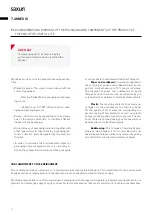
DISASSEMBLY AND REMOVAL OF THE PRODUCT
IMPORTANT
The disassembly of the product at the end
of its useful life must be carried out by
qualified personnel. In order to carry it out,
the steps that were carried out for its as-
sembly must be performed in reverse.
IMPORTANT
Always act with care.
Please only use suitable tools that are in
perfect condition.
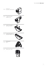
• Step 1
Close the canopy and remove the cable.
• Step 2
Loosen the screws on the covers of the aluminium
double poles and remove the covers.
• Step 3
Remove the double poles from the guides by loosening
the screws of the flanged pulleys that fix the poles to
the guides.
• Step 4
Loosen the screws and remove the plugs from the
double poles so that the canvas can be uncoupled.
• Step 5
Remove the plastic tubes from the canvas fold.
• Step 6
Loosen the screws that fix the guide profiles to the
guide supports and remove the profiles (in case of
wall-to-walls go directly to step 13).
• Step 7
Loosen the screws that fix the inner joint profile to the
structural tube.
• Step 8
Loosen the screws that fix the bar to the
inner joint profile.
• Step 9
Uncouple the beam from the bars and columns.
• Step 10
Loosen the screws that fix the columns to the foot
supports and decouple the columns.
• Step 11
Loosen the screws that fix the bars to the foot sup-
ports and decouple the bars.
• Step 12
Remove the beam covers.
• Step 13
Loosen the anchors of the floor foot and/or wall sup-
ports and uncouple the supports.
• Step 14
Loosen the screws that fix the fitting to the surface and
remove it.
• Step 15
Loosen the screws that fix the single and double trolley
to the surface and to the beam and remove them.
• Step 16
Finally, if you have a canopy, loosen the screws that
connect the canopy profiles and decouple them.
IMPORTANT
Ensure than you dispose of all pieces of the
product taking into account the nature of
their materials.
Summary of Contents for ANEAS
Page 1: ...TECHNICAL MANUAL ANEAS 80x40 ENG ...
Page 2: ......
Page 4: ...4 ...
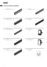
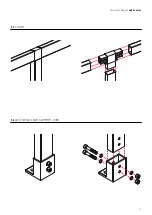
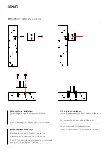
Page 14: ...14 5 1 ADJUSTABLE CORNER JOINT 5 2 FIXED CORNER JOINT 5 ASSEMBLY AND INSTALLATION ...
Page 15: ...TECHNICAL MANUAL ANEAS 80x40 15 5 3 T JOINT 5 4 CAST IRON FLOOR SUPPORT JOINT ...
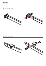
Page 16: ...16 5 5 FOOT SUPPORT JOINT 5 6 GUIDE SUPPORT JOINT ...
Page 17: ...TECHNICAL MANUAL ANEAS 80x40 17 5 7 CAPITAL JOINT 5 8 END HOOK GUIDE SUPPORT JOINT ...
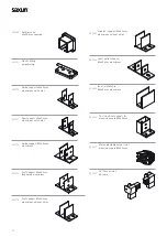
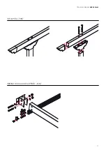
Page 18: ...18 5 9 SMALL PULLEY DETAIL DOUBLE TROLLEY INSTALLATION ...
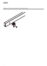
Page 19: ...TECHNICAL MANUAL ANEAS 80x40 19 5 10 CANOPY OPTION ...
Page 27: ...NOTES ...