background image

www.sawo.com

[email protected]

Subject to change without notice.

STP_ML(En0916)

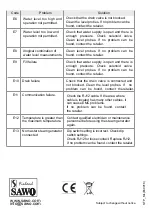
Code

Problem

Solution

Drain failure

E10

Communication failure.

E11

Temperature is greater than 

the maximum temperature.

E12

No master steam generator 

connected

 Dip switch setting is incorrect. Check dip 

switch settings. 

Check RJ12 for loose contact. Replace RJ12.

If no problem can be found, contact the retailer.

E13

Check the RJ12 cable. If the area where 

cable is located has many other cables, it 

can cause EMC problems. 

If  no  problem  can  be  found,  contact 

the retailer.

Check that the drain valve is connected and 

not blocked. Clean the level probes. If  no 

problem  can  be  found,  contact  the retailer.

Water  level  too  high  and 

operation not permitted.

E6

Water level too low and 

operation not permitted.

Check that water supply is open and there is 

enough  pressure.  Check  solenoid  valve. 

Clean  level  probes.  If  no  problem  can  be 

found, contact the retailer.

E7

Illogical combination of 

water level measurements.

Clean  level  probes.  If  no  problem  can  be 

found, contact the retailer.

E8

Fill failure

Check that water supply is open and there is 

enough  pressure.  Check  solenoid  valve. 

Clean  level  probes.  If  no  problem  can  be 

found, contact the retailer.

E9

Check that the drain valve is not blocked. 

Clean the level probes. If no problem can be 

found, contact the retailer.

Contact qualified electrician or maintenance 

personnel before using the steam generator 

again.

Summary of Contents for STP-120-3

Page 1: ... the steam generator STEAM GENERATOR 3 0 kW 3 5 kW 4 0 kW 4 5 kW 6 0 kW 7 5 kW 9 0 kW 12 0 kW 15 0 kW 4 5 kW 5 0 kW Models STP 30 1 2 STP 35 1 2 STP 40 1 2 STP 45 1 2 STP 50 1 2 STP 45 3 STP 60 3 STP 60 C1 3 STP 75 3 STP 75 3 C1 3 STP 90 3 STP 90 C1 3 STP 120 3 STP 150 3 Serial Number Serial Number Serial Number ...

Page 2: ...et 12 Steam Guard Overflow 12 Steam Head 12 Drain 13 Attaching Autodrain 13 Power Wiring 13 Technical Data 14 Electrical Diagram 14 Installing the Temperature Sensor 17 Installing Control Unit 18 Connection of SAWO 19 Terminal Connection of 20 On Off Mode Standby Mode Auto Drain Mode Temperature Timer Key Lock Changing the Values Optional Features Cabin Light Dimmer Fan Demand Button 7 Switching B...

Page 3: ...door flooring and ceiling Rubber linings e g gaskets are recommended for the door to effectively seal the heat and the steam inside the Steam Room If tiles are used for the flooring or some other smooth surface material provide suitable anti skid strips or rubberized mats to prevent slipping resulting to injury Materials used for the walls and ceiling should have water resistant non corrosive surf...

Page 4: ...nerator accessories Transformer Autodrain PCB cover Solenoid Valve Water Level Probe Steam Outlet Steam guard overflow For illustrative purposes only For illustrative purposes only Not for use for wiring For component identification only WARNING Power switch Alternative Drain outlet ...

Page 5: ...g On Off Mode On Off Mode On Mode When the power switch is turned On the software versions of the control board and the user interface will be displayed for 1 second each Then the control unit will go to Off mode In the Off mode the display is blank The auto drain can be disabled or enabled in the Off mode Press and hold the Up button then press the Power button The display will show Adr oFF or Ad...

Page 6: ...by pressing power button for more than 3 seconds To start Auto Drain in On mode press Power or Standby button followed by a long press more than 3 seconds of Standby button The temperature timer button can be used to switch between the temperature and session time When the steam generator is switched on the set temperature at the steam room is displayed It can be changed by pressing up and down bu...

Page 7: ... down button in the settings menu will in or decrease the currently displayed value A value cannot be in or decreased above or below its maximum or minimum value if it is tried low tone buzzer alarms the user If no keys are pressed within 5 seconds changes in the values are confirmed Optional features are not available in every model If dimmer feature is available press cabin light button to turn ...

Page 8: ...ivated every 20 mins and 20 pump on continuously If no keys are pressed within 5 seconds the previously displayed value will be shown again and the scent pump setting is saved If scent pump is on when the session time expires or the steam generator is turned off by pressing power button scent pump will turn off too Scent pump on and interval settings are saved and pump starts automatically on the ...

Page 9: ...recommended twice a year Please contact your service center for details SAWO Decalcifying Solution can be used for decalcification Follow these guidelines to perform preventative maintenance of the steam generator 1 Decalcification Turn on the steam generator and wait until water inside the tank starts to boil Turn off the generator Remove the cap of angled tube in the steam outlet piping Before o...

Page 10: ...ng generator s covers Only licenced electrician or professional maintenance person can open covers and do cleaning Clean level probe as stated in 2 a to 2 b Remove temperature fuse and tank temperature sensor from terminal block d e Remove the cassette where the heating elements are attached and clean deposits from the element Remove deposits from bottom and sides of the tank Open bottom plug to w...

Page 11: ...asoline paint thinners chlorine or the like Provide a level surface to install steam generator Side hole slots are provided for wall mounting Make sure that the steam generator is secured and is level when mounted on the wall The steam generator has to be installed in an upright position only Install water filter and softener or alike when necessary Leave enough space for service and maintenance o...

Page 12: ...quired for the STP steam generators is 2 8 bar or 30 120psi Below or above the pressure requirement may lead to damage or malfunction of the water inlet Steam Generator Thread 1 2 BSP Thread 1 BSP 3 0 kW 3 5 kW 4 0 kW 4 5 kW 5 0 kW 6 0 kW 7 5 kW 9 0 kW 12 0 kW 15 0 kW NOTE Refer to Technical Data for specifications Side view showing element access panel Overpressure Valve Steam Outlet Valve Thread...

Page 13: ...ipe or copper tubing for steam line to connect to the steam head as permitted by codes see table below Slope the steam line height by 20mm per meter towards the steam head to avoid trapping of the condensate and eliminate steam trap that blocks the flow of the steam Running the steam line down and then up will create a steam trap blocking the flow of the steam Recommended 300mm Steam Supply Instal...

Page 14: ...2 Attaching the Autodrain Drain Autodrain Top View 3 5 Terminal Block DRAIN An extra outlet for the autodrain can be found under the steam generator Attach the Brass tee into the outlet that can be found on under and on the side of the steam generator An extra outlet for the autodrain can be found under the steam generator Attach the autodrain to the brass tee Open the cover of the steam generator...

Page 15: ...415 STP 45 3 4 5 2 5 540 245 470 540 210 470 STP 50 1 2 5 0 2 6 540 245 470 3N STP 60 3 6 0 3 10 6 0 2 5 4 0 4 0 2 5 1N 3N 3 16 20 220 240 220 240 3 20 220 240 380 415 220 240 380 415 27 9 540 245 470 STP 60 C1 3 6 0 3 10 540 245 470 STP 75 3 7 5 4 15 6 0 2 5 1N 3N 20 34 11 540 245 470 STP 75 C1 3 7 5 4 15 STP 90 3 2 5 3N 380 415 13 540 295 470 9 0 8 20 23 STP 90 C1 3 10 0 2 5 1N 3N 220 240 3 23 2...

Page 16: ...H PL N G CONTACTOR TRANSFORMER L3 L2 L L1 N G L3 L2 L1 HEATING ELEMENTS 5 core cable HEATING ELEMENT H1 H2 H3 4 core cable 3 core cable 6 0 kW 7 5 kW 380 415V 3N S WATER FEED SOLENOID VALVE CONTROL BOARD GROUND 230VAC in FAN SCENT PUMP 24VAC IN CONT DRAIN FILL PE PROBE1 PROBE2 PROBE3 LIGHT SWITCH L3L2L1 N G FUSE NTC2 TRANSFORMER FUSE NTC2 TEMP Fan 100W Light Scent Pump Auto Drain 12V DC Switch Tem...

Page 17: ...SWITCH PL N G CONTACTOR TRANSFORMER L3 L2 L L1 N G L3 L2 L1 HEATING ELEMENTS H1 H2 H3 H4 H5 H6 5 core cable 4 core cable 3 core cable 9 0 kW 380 415V 3N C CONTACTOR S WATER FEED SOLENOID VALVE CONTROL BOARD GROUND 230VAC in FAN SCENT PUMP 24VAC IN CONT DRAIN FILL PE PROBE1 PROBE2 PROBE3 LIGHT SWITCH L3L2L1 N G FUSE NTC2 TRANSFORMER FUSE NTC2 TEMP Fan 100W Light Scent Pump Auto Drain 12V DC Switch ...

Page 18: ...ng should not be routed near power cables or hot areas as it may cause electronic interference or damage to the wires An 25mm hole is required to insert the temperature sensor Do not create bigger or smaller hole Clean the hole before inserting the sensor Make a hole in the cable lead in on the side of the generator to pull the cable through Connect the cable in the terminal block marked as TEMP S...

Page 19: ...Do not install the control unit inside the steam room The cable of the control is 7 5 meters Mount the control in the wall according to the specifications given below Follow illustra tion SAWO Steam Control sets the temperature of your steam room Mount the steam control unit on an accessible area outside the steam room It is recommended not to place the steam control near to showers or similar wet...

Page 20: ...ected to either of these jacks the order is insignificant Unscrew PCB cover on the side of the generator to get access on the PCB Guide the RJ12 control cable through the cable lead in hole on the side of the generator and then behind the side panel as described in the drawing below to reach RJ jacks on the corner of PCB Fasten the PCB cover and the top cover of the generator Turn the mains on and...

Page 21: ...onal dimmer in steam genera tor make sure that the ligths are dimmable before connecting Steam genera tor uses phase control to regulate power for lighting Fan optional Light Scent Pump optional Before installation make sure that the mains is disconnected from the generator by turning off the circuit breaker 1 Open the top cover of the generator Guide the cable through cable lead in on the side of...

Page 22: ...Light 7 6 5 4 3 2 1 30 55 C Dimmer option enabled Dimmer option disabled Present Present Connected Yes 30 50 C Not Present Not Present Not Connected No Fan Scent Pump Auto Drain Temperature range Slave Unit Slave Number Slave Number Standby time can be set according to user preferences by setting dip switches on the power controller board Session time can be set according to user preferences by se...

Page 23: ... sensor 2 not connected E3 Code Problem Solution Temperature sensor 2 short circuit E4 22 Steam Generator Control Master Steam Generator DIP SW 3 OFF DIP SW 3 ON 2 OFF 1 OFF DIP SW 3 ON 2 ON 1 OFF Slave 1 Steam Generator Slave 2 Steam Generator Slave 3 Slave 4 RJ12 Cable If an error occurs the steam generator will be switched off There will be a warning beep to alarm the user every 2 seconds The c...

Page 24: ...level probes If no problem can be found contact the retailer Water level too high and operation not permitted E6 Water level too low and operation not permitted Check that water supply is open and there is enough pressure Check solenoid valve Clean level probes If no problem can be found contact the retailer E7 Illogical combination of water level measurements Clean level probes If no problem can ...

Reviews: