


w w w . s a t l a b g p s . c o m
2 7
SLC GNSS RECEIVER
Internal GSM NTRIP
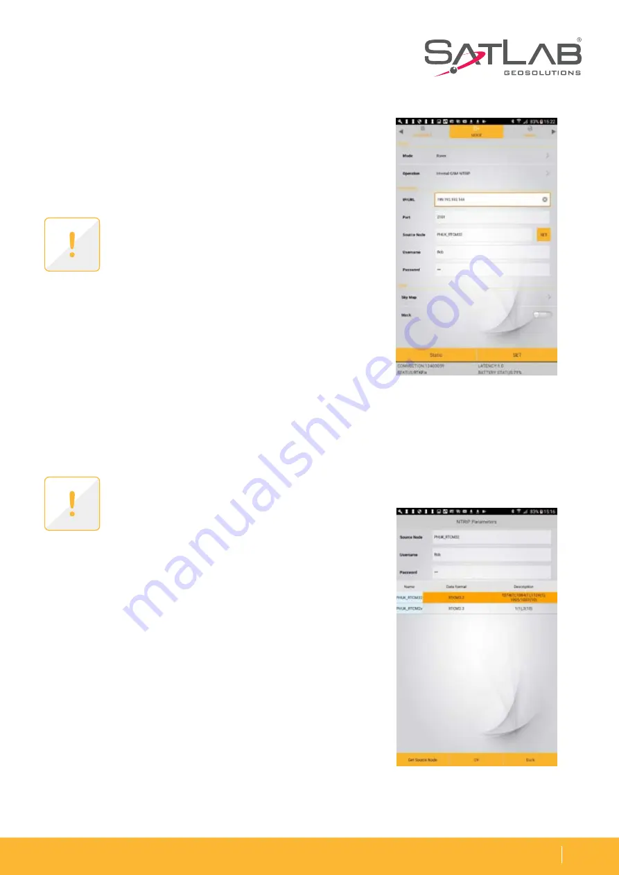
The following figure shows the NTRIP configuration page when
Rover/Internal GSM NTRIP is selceted. Enter the Network IP
address, Port number and your User name and Password.
Selecting the Mount Point
(Source Node)
To select the required Mountpoint (Source Node) click on the ‘SET‘
button next to the ‘ Source Node‘ box on the configuration page
and the following page will appear.
Note: The Source Node can be typed into the
Source Node box or can be selected per the
proceedure described on following page.
Note: NTRIP configuration for
Data Collector
NTRIP is same with exception the internet
connection is via the Tablet modem.
Once all the settings are confirmed click ‘SET‘ to configure the
receiver for connection to the Network. The settings will be
confirmed with the message Set Successful.
Watch the status on the bottom of the setting page, and the
signal LED on the top right of SLC. If your connection to NTRIP
network is successful, the signal LED will change to solid GREEN
and when data is received it will flash YELLOW.
1. Click on ‘Get Source Node‘ at bottom left of the page and the
Source table for the Network will appear.
2. Next click on the required Mount point then click OK to
select and it will populate the Source Node box at top of page.
3. Click on OK bottom middle of page to confirm the selection.
4. Click Back at bottom right to return to the NTRIP config page.
On your tablet PC the STATUS on the bottom will show Latency time and STATUS will change from Single over
to RTD, RTK Float to RTKFix. An indicator of correction quality is the value of latency in seconds which should
be fluctuating between 1 to 2 seconds in ideal case.
Figure 3-16
Figure 3-17