


41
3.10
Ladder diagrams
See chapter
2.5.2 of this document to get basic information about
implementation of ladder diagrams in PLC Configurator.
Basic concepts are similar to creating FBD. We suggest you to read
chapter
3.9 first, then proceed to this chapter.
3.10.1
Add ladder diagram
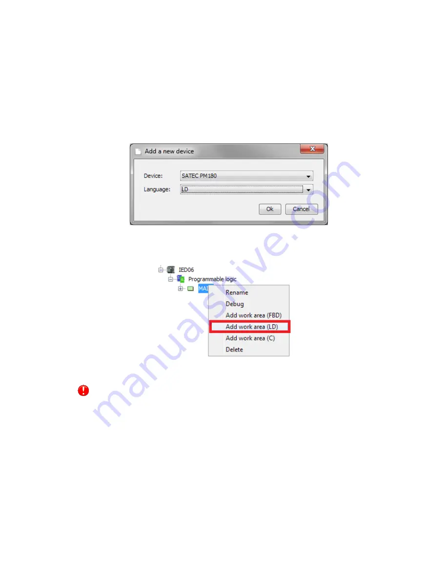
To create a ladder diagram you need to add a device in your project
and choose LD language in the window shown in the figure below.
Figure 58 - Add new device with LD
If you want to add a ladder diagram to existing function block, just click
with the right mouse button on the function block and choose “Add
work area (LD)”.
Figure 59 - Add work area (LD)
You can use FBD and LD workspaces together in one function block
and divide information between them if it is necessary.
After creating a workspace use double-click on it to open.
A ladder diagram consists of elements such as rails, contacts, coils. Also
it can contain built-in functions (see
2.3).
All elements have pins. Pins can be attached or unattached. Attached
pin are marked as green circle, unattached is marked as red circle.
To add any element to a ladder diagram (excluding rails) you need to
drag-and-drop variable from variables list. Input, output and local
variables are allowed.


