21
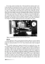
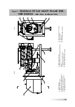
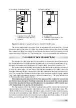
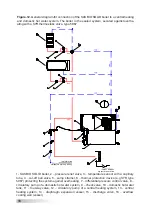
Figure 7.
DIAGRAM OF SAS MULTI FLAME BUR-
NER DESIGN
- side view, sectional view
1. Furnace housing 2. Heater (electric
burner)
3. Fuel f
eeder (two tr
ansport augers
separ
ated
by the tr
ansfer duct)
4. Fuel f
eeder temper
ature sensor
5. Mo
ving gr
ate driv
e
motor
6. F
eeder
supporting f
oot
7. Hall eff
ect sensor
(mo
ving
gr
ate
positioning
sensor) 8. Thermally insulated
air
duct
9. Furnace housing br
ack
et
10. Shape made
of
cer
amic material
11.
The air supply to the
furna
ce
12.
Furnace
spa
ce
13.
Blow
duct
14.
Air
chamber
clean out
hatch

