2
Copyright © 2020 SARGENT Manufacturing Company. All rights reserved. Reproduction in whole or in
part without the express written permission of SARGENT Manufacturing Company is prohibited.
1-800-727-5477 • www.sargentlock.com
A7133 12/20
10 Line
Installation Instructions
Cylindrical Lockset
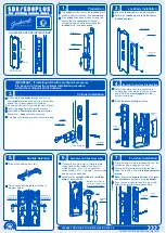
Figure 5
Install screws (2) #8-32 x 3/4". Tighten after adjustment
Note: On doors without a beveled edge, the lock needs to be
adjusted to center the latch. Adjust per Section 5.
Presets:
• Through-bolt location: 12 and 6 o’clock. (Figure 6)
• Door Thickness: 1-3/4" thick.
Figure 6
See step 10 for other door conditions
Outside
of Door
• Remove outside lever (usually keyed), rose and spacer bushing.
(Figure 8)
• Rotate mounting plate to align with through-bolt holes in door, or
adjust mounting plate for proper door thicknesses (see markings
on Figure 7).
• Reinstall spacer bushing to align with back of lever. Reinstall scalp
and lever.
• For doors 1 3/8" thick, use the 10-3188 adapter kit sold separately.
Confirm latch bolt front size.
Figure 7
Figure 8
Mounting plate
with through-bolts
Through-bolt
holes
Spacer bushing
1-3/4" thick door
2" thick door
NOTE: Test for proper
operation before closing
door.
3
Latch Installation
4
Install Outside Assembly
5
Through-bolt and door thickness adjustment other than preset
6
Install Inside Rose Assembly, Scalp and Lever


