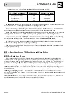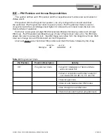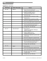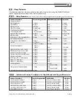
3
630-600
MODEL 6128/6129 PROGRAMMING & OPERATIONS GUIDE
GENERAL INFORMATION
1
.
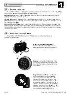
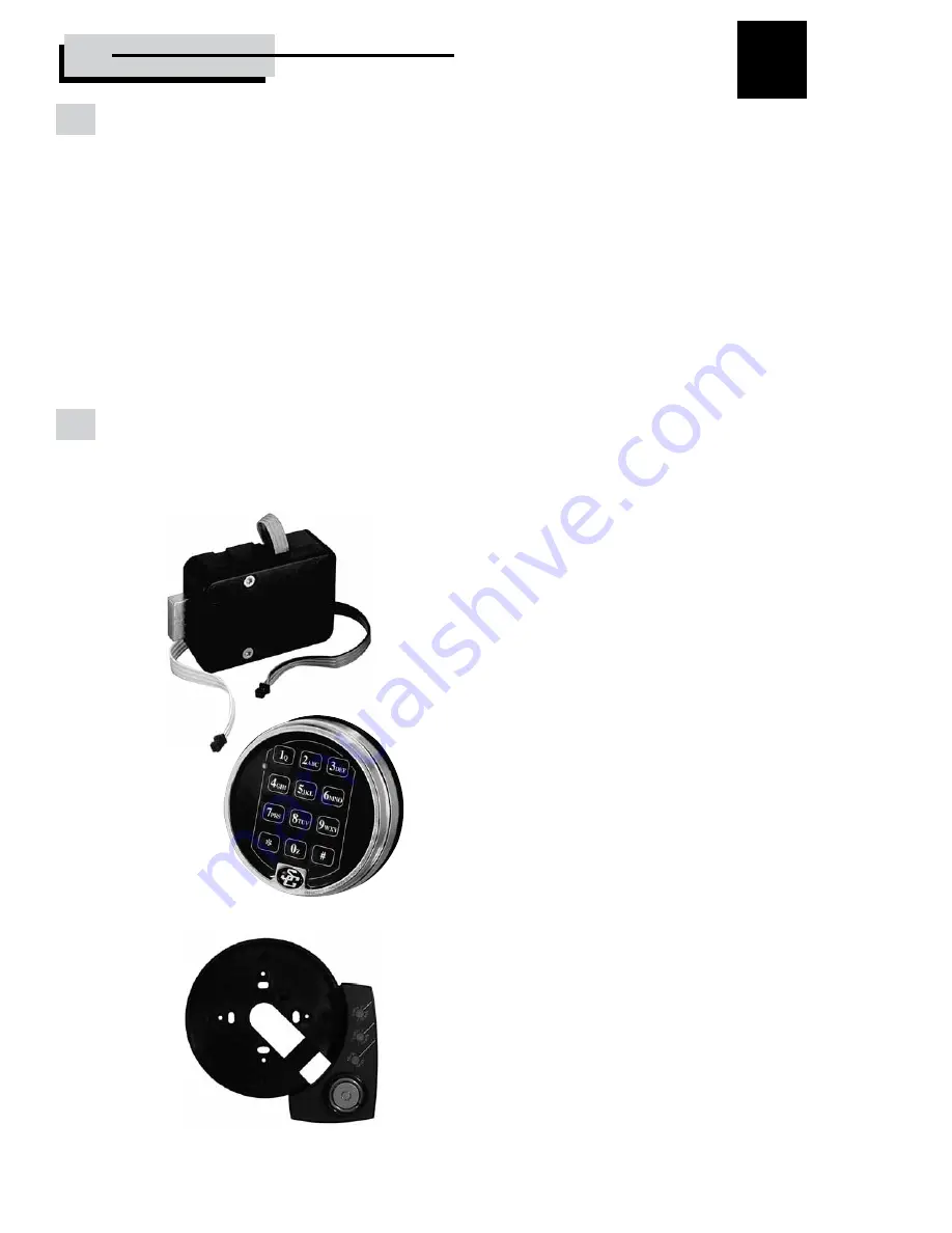
6128 /6129 Motorized lock —
housed within the safe . Provides for
Bank and Service modes of operation .
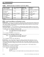
Keypad Extension Base —
Installed
under the keypad . This is required
when using the lock’s Service Mode
operation or audit trail function . The
extension base provides a green LED
to indicate “Status 1”, and a red LED to
indicate “Status 2” and a yellow LED to
indicate “Mode” of lock operation . The
extension base also provides a port for
communication with Touch Keys .
Keypad —
on front of safe door . This
is a 12-key alphanumeric keypad used
to enter PIN codes and programming
commands .
1.1 — Security Hierarchy
The Model 6128 ATM banking lock system operates in a Bank Mode only, Service Mode
only, or both Bank and Service Mode simultaneously .
Bank Mode Only
- Bank users have local control of user PIN positions and codes, and
programming through the keypad .
Service Mode Only -
Requires the “Lock Management System” for programming Touch
Memory Keys and generating one-time use Operation codes for service users . Bank User
PIN codes are disabled .
Bank and Service Mode -
Bank users have local control of PIN positions and codes, and
limited keypad programming commands . The “Lock Management System” controls Bank
mode optional features and is used for programming Touch Memory Keys and generating
one-time use codes .
1.2 — About Your Locking System
The Model 6128/6129 Comptronic™ Electronic Lock has the following
hardware components:


