background image

4

Sargent and Greenleaf

Revision 02/15/2022 Document: 630-600

1 - General Information

1.1— About Your Locking System

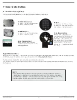
The Model 6128/6129/6106 Electronic Lock has the following hardware components:

6128 /6129 Motorized lock

housed within the safe. Provides for Bank 

and Service modes of operation

Keypad

on front of safe door. This is a 12-key 

alphanumeric keypad used to enter PIN 

codes and programming commands.

6106 Pivot bolt lock

housed within the safe. Provides for Bank 

and Service modes of operation

Duress Module (optional)

Housed within the safe. this module 

must be connected to the lock to use the 

duress alarm feature.

Keypad Extension Base 

Installed under the keypad. This is 

required when using the lock’s Service 

Mode. The extension base provides a 

green LED to indicate “Status 1”, and 

a red LED to indicate “Status 2” and a 

yellow LED to indicate “Mode” of lock 

operation. The extension base also 

provides a port for communication with 

Touch Keys.

Keypad Extension Base 

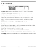
Each time you press a number, letter, or other character on the keypad, it beeps and the keypad’s red LED fl ashes. If there is no beep 

or LED fl ash, check the batteries and try again (See section 2.10 — Changing the Batteries).

The # key acts as an enter function and must be used after each code entry.

The * key is used with Programming Command Codes. It may also be used to clear the keypad if there is an input error, by entering 

the * key twice.

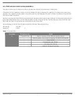
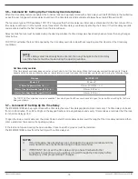
NOTE:

The lock resonds with different beep sequences to indicate different conditions. 

The beeps are indicated in the examples by the symbol 

. For example, fi ve beeps 

are indicated by 

♪♪♪♪♪

. Always wait for each set of beeps to end before entering 

another number or letter or you will interrupt the lock’s instructions.

Summary of Contents for 6106-240 A Series

Page 1: ...y affect the cable connector or the keypad receptacle Each time a button is pressed and the lock accepts the input it emits a beep and the LED on the keypad lights momentarily All the letters of the English alphabet are displayed on the keypad This allows you to devise numeric alphanumeric or word based codes Use whatever approach works best for you All codes end with This signals the lock that yo...

Page 2: ...Battery Indicator 11 2 10 Changing Batteries 11 2 11 iButton Touch Key 11 3 PROGRAMMING THE LOCK IN BANK MODE 12 3 1 Command 22 33 Changing a PIN Code 12 3 2 Command 32 Setting the Access Mode 12 Enable the Manager Employee Mode Enable the Dual Control Mode Enable Multiple User Mode Enable the Dual Control Mode 2 3 3 Command 38 Setting the Duress Alarm Feature 13 Using the Duress Alarm Feature Ena...

Page 3: ...20 3 21 Command 00 Manual Secure Mode 20 4 SERVICE MODE OPERATION 21 4 1 Service Mode Initialization 21 4 2 Service Mode Operation 21 4 3 Service Mode Operation Codes 22 4 4 Open Lock 22 Single Control Single control 15 minute Dual Control 4 5 Program Bank Features 23 4 6 Download Audit Log 23 4 7 Reset User Touch Key 23 4 8 Using the Duress Alarm Feature 23 4 9 Set Clock Calendar 24 Red Manager K...

Page 4: ...reen LED to indicate Status 1 and a red LED to indicate Status 2 and a yellow LED to indicate Mode of lock operation The extension base also provides a port for communication with Touch Keys Keypad Extension Base Each time you press a number letter or other character on the keypad it beeps and the keypad s red LED flashes If there is no beep or LED flash check the batteries and try again See secti...

Page 5: ...and generating one time use Operation codes for service users Bank User PIN codes are disabled Bank and Service Mode Bank users have local control of PIN positions and codes and limited keypad programming commands The Lock Management System controls Bank mode optional features and is used for programming Touch Memory Keys and generating one time use codes 1 3 Factory Default Settings The 6128 6129...

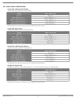
Page 6: ...condition We recommend that Users change their PIN Codes immediately after the PIN positions are assigned 2 1 Bank User Group Bank User Group is the factory default and is always active in each lock unless disabled under Service Mode operation The Bank User Group has an access hierarchy of Officers PIN positions 01 03 Administrators PIN positions 04 09 and Users PIN positions 10 29 See Tables A B ...

Page 7: ...ation Number position and a 6 digit PIN Code The PIN position identifies the type of User Programmer User etc The PIN Code allows the User to access the lock Together these two codes form the 8 digit User Code Each User can change his own PIN Code but not his PIN position Users will always enter both their PIN position and their PIN Code followed by the key PIN POSITION PIN CODE Example 02 020202 ...

Page 8: ...d second User Code for Dual Control and programming Change their own PIN Code 04 09 Administrators Open the lock Except when Manager Employee Mode is enabled Enable disable Users in Manager Employee Mode Delete Users requires a second valid User Code Start time delay when programmed Send duress alarm when programmed Can be a valid second User Code for Dual Control and programming Change their own ...

Page 9: ...input Lock in 10 minute penalty time 2 brap 1 cycle Code input Lock Disabled 2 beep2 Red 1 cycle Enable lock mgr emp mode 4 beep1 1 cycle Disable lock mgr emp mode 2 beep2 1 cycle Access to program modes 5 beep1 Green 1 cycle Program argument confirmation 3 beep1 1 cycle Program complete 3 beep1 Green 1 cycle First user entry dual control 4 beep1 Red 1 cycle Mode 77 PIN used 1 beep2 Red 1 cycle Mo...

Page 10: ...one code is required to start the time delay but both codes must be entered during the opening window to open the lock Time Delay The lock may be programmed with a time delay from 0 99 minutes with an opening window of 1 minute to 10 minutes If your lock does not use the time delay Enter Your 2 digit PIN position Your 6 digit PIN Code After the beeps turn the safe handle to the unlocked position w...

Page 11: ...tery Indicator If you enter a correct User Code and hear 5 double beeps when the lock opens the batteries are low Change the batteries If the batteries are so low the lock can t work properly the lock beeps 20 times when a User code is entered The lock will not open Change the batteries right away and re enter a User code to open the lock The 9V batteries are located behind the keypad 2 10 Changin...

Page 12: ...red within 60 seconds after entry of the first code If time delay is activated only one code is required to start the time delay but both codes must be entered during the opening window to open the lock Multiple User The lock can be opened by entering any valid code except for the Programming Code Enable the Manager Employee Mode Set the lock into Manager Employee mode by performing the following ...

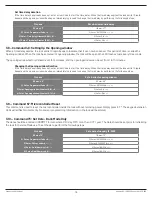
Page 13: ...nds in 0 use 1 or 9 to activate the duress alarm The lock will operate normally when a Duress code is entered All User Codes can send the duress signal at any time It can also be sent during programming sequences Enable the Duress Alarm Feature After the lock is installed with the module the duress feature must be enabled by performing the following steps Enable the Duress Alarm Feature After the ...

Page 14: ...aintained in the lock firmware The serial number cannot be change If the key is programmed with the incorrect serial number when trying to utilize the single initialization process the lock will fail to initialize The key is not programmed with serial number information when performing the multiple initialization process To initialize multiple locks Command 45 1 Set the date time using the 73 comm...

Page 15: ...E 2 function has now been enabled The code in position 29 can now be used to open the lock without waiting for the time delay countdown 3 7 Command 47 Setting Up the Time Delay The 6128 6129 6106 can be programmed with a time delay feature Time delay applies to Bank Users only The time delay can be set from 0 to 99 minutes The LED red light on the keypad flashes and a single beep sounds every 10 s...

Page 16: ...mmediately proceed to change the time delay by performing the following steps 3 9 Command 57 Microcontroller Reset This command is used to reset the microcontroller inside the lock without removing power Simply press 5 7 The keypad extension LEDs will all flash momentarily No code or programming information in the lock will be altered 3 10 Command 73 Set Date Bank Mode Only The date should be ente...

Page 17: ...ange his or her PIN Code using Command 22 Process Delete a code in pin 12 1 Enter 74 1 Enter 74 2 Enter Officer Code 2 Enter 02020202 3 Enter A valid second code 3 Enter 10101010 4 Enter User position 4 Enter 12 5 Enter User Position 5 Enter 12 Process Create a code in pin 13 1 Enter 75 1 Enter 75 2 Enter Officer Code 2 Enter 02020202 3 Enter empty pin position 3 Enter 13 4 Enter A new 8 digit cod...

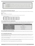
Page 18: ...l to place a touch key user of manager key onto the keypad extension and input 8 2 The lock will write an audit trail event to the touch key indicating the lock ID and current time date stored in the lock The lock will emit 3 beeps after writing the even to the key If the 8 2 command is used with a touch key that is disabled the lock will emit 2 low beeps but will still write the event to the touc...

Page 19: ...k s Aseal close code can be audibly retrieved when there is not any visual indicator available The lock will give a low beep for the number 0 and 1 beep counting up any number great than 0 The lock will pause between each number You can verify the lock serial number using the following process Enter 93 on the lock keypad Aseal 103968 Process Set a 5 minutes time delay 1 Enter 83 1 Enter 83 2 Enter...

Page 20: ...ual indicator available The lock will give a series of low beep and high beeps that represent the lock format of DDMMYY HHmm You can verify the lock time and date setting by using the following process Enter 97 on the lock keypad DATE 23 01 22 11 23 AM 3 21 Command 00 Manual secure mode The A Series lock can be configured to operate a Manual Secure Mode IN this mode it requires the user to enter t...

Page 21: ... Mode indicator during processing of code 5 If the operation is verified and allowed by the lock the response will be three Green Status 1 indicator flashes along with three beeps If the request is denied the Red Status 2 indicator will be used in conjunction with a beep pattern to indicate code failure Reference Beep Patterns to identify the failure condition 6 User removes touch key 4 2 Service ...

Page 22: ...in reader 6 User 2 inputs four digit PIN and presses the key 7 User 2 inputs the eight digit operation code and presses the key 8 Lock illuminates Amber Mode indicator during processing of code 9 Lock indicates successful result with Green Status 1 and three beeps 10 Lock unlocks and User may open the door 11 When the door is closed the bolt will extend and the lock prompts the user to present the...

Page 23: ...git twice followed by any valid operation code If your PIN is 1234 and your operation code is 12345678 you would enter 12344 12345678 This would send the duress signal store a duress event in the touch key audit trail and store a duress event in the lock audit trail 4 8 Set Clock Calendar with Manager Key This is a management only operation code that is used to reset the clock calendar setting ins...

Page 24: ...pad HHmm and presses the again to confirm Lock responds with Green Status 1 indicator and emits three audible beeps 4 10 Reset Lockout This is a management only operation code This operation is used to reset the lock once it is set in a lockout mode due to excessive unauthorized attempts to operate the lock with invalid operation codes or bank user PIN codes This code will not open the lock 4 11 R...

Reviews: