background image

PB-CI7S41X58 Mainboard 


~ 10 ~ 


2-5 Installing System Memory 

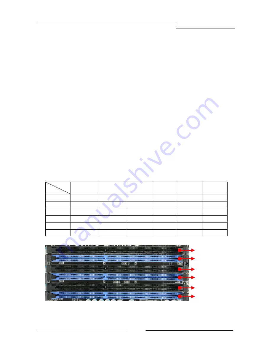
This mainboard has six 240-pin DIMM sockets for DDR3 memory. These slots 
support 1GB, 2GB and 4GB DDR3 DIMMs. 
Make sure that you install memory modules of the same type and density in 
different channel DIMM slots for Triple-Channel/Dual-Channel mode. 
There must be at least one memory bank populated to ensure normal operation 
and always inset the memory module into the DIMM slot 1 first. 

Memory configurations: 

Use the following the recommendations for installing memory. 
1 DIMM (Single-Channel):  install into DIMM slot 1.   
2 DIMMs (Dual-Channel):  install into DIMM slots 1 and 3. 
3 DIMMs (Triple-Channel): install into DIMM slots 1, 3 and 5. 
4 DIMMs (Triple-Channel): install into DIMM slots 1, 3, 5and 2. 
5 DIMMs (Triple-Channel): install into DIMM slots 1, 3, 5, 2 and 4. 
6 DIMMs (Triple-Channel): install into DIMM slots 1, 3, 5, 2, 4 and 6. 

DIMM Qty 

 
Location 

1 DIMM 

(Single Channel) 

2 DIMMs 

(Dual Channel) 

3 DIMMs 

(Triple Channel) 

4 DIMMs 

(Triple Channel) 

5 DIMMs 

(Triple Channel)


6 DIMMs 

(Triple Channel) 

DIMM#2 

-- 

-- 

-- 

DIMM#1 

DIMM#4 

-- 

-- 

-- 

-- 

DIMM#3 

-- 

DIMM#6 

-- 

-- 

-- 

-- 

-- 

DIMM#5 

-- 

-- 


DIMM#2 

DIMM#1 

DIMM#3 

DIMM#4 

DIMM#6 

DIMM#5 

Summary of Contents for PB-CI7S41X58

Page 1: ...S41X58 Intel X58 LGA1366 Series Mainboard TRADEMARK All products and company names are trademarks or registered trademarks of their respective holders These specifications are subject to change withou...

Page 2: ...ving antenna Increase the separation between the equipment and receiver Connect the product into an outlet on a circuit different from that to which the receiver is connected Consult the dealer or an...

Page 3: ...k 9 2 5 Installing System Memory 10 Memory configurations 10 Memory Installation 11 2 6 Installing Expansion Cards 12 PCI E Slots 12 PCI Slot 13 2 7 Connecting Cables 13 Connecting Power Supply Cables...

Page 4: ...4 Advanced Menu 32 IDE Configuration 33 Hardware Health Configuration 34 USB Configuration 35 ACPI Configuration 36 Intel VT d Configuration 37 PCI Express Configuration 37 Onboard Device Configurati...

Page 5: ...nel two onboard by header supporting transfer speeds up to 480Mbps Two USB 3 0 ports at rear panel backwardly compatible with USB 2 0 supporting transfer speeds up to 4 8Gbps Supports wake up from S1...

Page 6: ...IF Coaxial output Supports Jack detection function Expansion Slots Four PCI Express x16 connectors Supports ATI CrossFireXTM Technology One PCI slot BIOS 8Mb SPI Flash with AMI based BIOS Supports ACP...

Page 7: ...1X58 Mainboard 3 1 2Package Contents Your Sapphire Pure Black X58 mainboard comes with the following accessories 1 Mainboard 2 Quick Installation Guide 3 Driver CD 4 I O Shield 5 SATA Data Cable 6 6 I...

Page 8: ...PB CI7S41X58 Mainboard 4 1 3Mainboard Layout The following figure shows the location of components on the mainboard See Page 5 for the Key...

Page 9: ...r 7 PCI E x16 Slots1 4 8 PCI Slot 9 IDE Connector 10 SATA3 Connectors 2 11 SATA2 Connectors 5 12 Front Panel Header 13 USB Header 14 IEEE1394a Header 15 Power Button 16 Reset Button 17 Clear CMOS Butt...

Page 10: ...ier through a coaxial cable 3 Optical S PDIF Out This SPDIF Sony Philips Digital Interconnect Format connector is used for digital audio transmission to external speakers amplifier through an optical...

Page 11: ...rts This mainboard provides 2 6 or 8channel audio It is easy to differentiate between the audio functions by referring to the color of the jacks Ports 2 channel 6 channel 8 channel Blue Line In Line I...

Page 12: ...technician Damage to system components the mainboard and injury to you may result if power is applied during installation 2 2 Installing the I O Shield The mainboard comes complete with an I O shield...

Page 13: ...e the cover unless the CPU is installed 2 Align the CPU notches to the socket protrusions Place CPU straight down without tilting or sliding it 3 Close the load plate and engage the socket lever 4 To...

Page 14: ...following the recommendations for installing memory 1 DIMM Single Channel install into DIMM slot 1 2 DIMMs Dual Channel install into DIMM slots 1 and 3 3 DIMMs Triple Channel install into DIMM slots 1...

Page 15: ...s mainboard To make sure you have the correct DIMM check that all the notches line up with the DDR3 DIMM slot To install the DIMM follow these steps 1 Pull both clips on either side of the slot outwar...

Page 16: ...ation VGA card PCIE1_x16 Blue PCIE2_x8 Blue PCIE3_x8 Blue 1 VGA card x16 2 VGA cards x16 x8 3 VGA cards x16 x8 x8 To install a PCI Express card 1 Place the card in an available PCI Express slot and pr...

Page 17: ...TX Power PW1 is the main power supply connector Make sure that the power supply cable and pins are properly aligned with the connector on the mainboard Firmly plug the power supply cable into the conn...

Page 18: ...cumentation for the jumper settings Connecting Serial ATA SATA Cables SATA cables support the Serial ATA protocol Each cable can be used to connect one internal SATA drive to mainboard The SATA2 0 SAT...

Page 19: ...ink S4 The LED is off PW_ON Attach the power button cable from the case to these two pins Pressing the power button on the front panel turns the system on and off rather than using the onboard button...

Page 20: ...with the front panel option 2 Connect the cable s to the USB 2 0header on the mainboard Note Please do not connect a 1394 cable to USB connector which will cause damage to the mainboard 1394 Header T...

Page 21: ...This header allows you to connect the front panel audio The audio connector supports HD audio standard S PDIF Header This header is used to connect S PDIF Sony Philips Digital Interconnect Format int...

Page 22: ...controlled and displayed in the Hardware Health Configuration section of the CMOS Setup The fans are automatically turned off after the system enters S3 S4 or S5 mode CPUFAN SYSFAN1 PWRFAN AUXFAN SYSF...

Page 23: ...has fully booted into the operating system 2 9 LED Status Indicators This mainboard provides three LEDs to indicate the system s status POWER LED LED3 Green When the System is powered on This LED is o...

Page 24: ...MOS can be cleared by pressing the Clear CMOS button Reset and Power Button These onboard buttons allow you to easily turn on off the system and allow for easy debugging and testing of the system duri...

Page 25: ...BIOS is corrupted or failed you can use the secondary BIOS to take over on the next system boot to ensure normal system operation To enable the secondary BIOS please refer to the following steps 1 Tu...

Page 26: ...that you do not change the default BIOS settings Changing some settings could damage your computer Note2 The BIOS options in this manual are for reference only BIOS screens in manuals are usually the...

Page 27: ...the system date The format is Day Month Date Year Day Weekday from Sun to Sat this is automatically displayed by BIOS Month The month from 1 to 12 Date The date from 1 to 31 can be keyed by numeric fu...

Page 28: ...ou to select the Memory Frequency Options Auto Force DDR 800 Force DDR 1066 Force DDR 1333 Main Advanced PCIPnP Boot Security Exit BIOS SETUP UTILITY Performanc e Frequency Voltage Configuration Manuf...

Page 29: ...ncore Frequency the Uncore clock must be at least 2x DRAM clock for overclocking Load Profiles Allows you to load the BIOS settings saved in the BIOS Flash Press Enter to load the file Options Profile...

Page 30: ...ttings Module version 01 0C CPU Revision B1 Manufacturer Intel Intel R Xeon R CPU X5680 3 33GHz Frequency 3 33GHz BCLK Speed 133MHz Cache L2 384 KB Cache L2 1536 KB Cache L3 12288 KB Ratio Status Unlo...

Page 31: ...TurboMode tech Enables the Intel Turbo Mode technology Turbo mode allows processor cores to run faster than marked frequency in specific condition Options Enabled Disabled Performance Watt select Aut...

Page 32: ...tRP Set the Row Precharge time This is the Precharge to Active or Auto to Refresh of the same bank Options 3 15 0 by auto detection Main Advanced PCIPnP Boot Security Exit BIOS SETUP UTILITY Performan...

Page 33: ...detection tWR Set the tWR values Options 3 11 0 by auto detection tWTR Set the tWTRvalues Options 4 31 0 by auto detection tRRD Set the tRRDvalues Options 4 15 0 by auto detection tRTP Set the tRTPva...

Page 34: ...rrent DIMM Voltage Displays the current DIMMvoltage Main Advanced PCIPnP Boot Security Exit BIOS SETUP UTILITY Performanc e Voltage Configuration Loadline Control Enabled 100 CPU Thermal Enabled Curre...

Page 35: ...QPI PLL Displays the current QPI PLL voltage QPI PLL Allows you to adjust the QPI PLL voltage Options 1 100V 1 450V in 0 025V increments Current IOH ICH IO Voltage Displays the current the Intel IOH...

Page 36: ...n menu is to set up onboard peripherals such as IDE RAID USB LAN and MAC control and to monitor the real time system status of your PC including temperature voltages and fan speed Main Performance PCI...

Page 37: ...ill need to change 2 items in BIOS settings please refer to the instructions below 1 Set the Configure SATA 1 as item from IDE to AHCI setting 2 The Hot Plug item appears select Enabled SATA 2Configur...

Page 38: ...Chassis Fan Speed 2029 RPM VCore 1 164 V VDimm 1 505 V VTT 1 259 V NB 1 111 V 5V 5 045 V 12V 12 320 V VCC3 3 312 V 3VSB 3 360 V VBAT 3 216 V CPU Fan Type PWM FAN 4 pin CPU Fan Mode Setting SmartFan T...

Page 39: ...AN 3 pin CPU Fan Mode Setting This item controls the speed of the various fans on the motherboard Choose SmartFan when you want the speed of the fans automatically controlled based on temperature To s...

Page 40: ...esume This item determines whether to invoke VGA BIOS POST on S3 STR resume Options No Yes ACPI Version Features Selects the ACPI version Enable RDSP pointers to 64 bit fixed system description tables...

Page 41: ...P UTILITY Advanced Intel VT d Configuration Intel VT d Disabled v02 69 C Copyright 1985 2010 American Megatrends Inc Disabled Enabled Select Screen Select Item Change Option F1 General Help F10 Save a...

Page 42: ...8 bit TAG field as a requester Options Auto Enabled Disabled No Snoop Enables the No Snoop function of PCI Express device Options Auto Enabled Disabled Maximum Read Request Size Sets the Maximum Read...

Page 43: ...Enabled Disabled Giga Lan PXE Boot ROM Enables the Giga Lan PXE Boot ROM Options Enabled Disabled C80P Show CPU Temperature Enables the onboard POST Port LED to display CPU temperature Options Enabled...

Page 44: ...em is used to specify DMA channel available to be used by PCI PnP devices or select Reserved for Legacy ISA devices Options Available Reserved Main Performance Advanced Boo Security Exit BIOS SETUP UT...

Page 45: ...69 C Copyright 1985 2010 American Megatrends Inc Configure Settings during System Boot Select Screen Select Item Change Option F1 General Help F10 Save and Exit ESC Exit Main Performance Advanced PCIP...

Page 46: ...ons On Off PS 2 Mouse Support Selects support for PS 2 mouse Options Auto Enabled Disabled Wait For F1 If Error Allows the system wait for the F1 key to be pressed when error occurs Options Enabled Di...

Page 47: ...password Change User Password To set a User Password 1 In the password box key in a password number then press Enter 2 Confirm the password when prompted 3 The message Password Installed appears afte...

Page 48: ...modifications Discard Changes Allows you to discard the selection you made Select OK or F7 or to discard all changes Load Optimal Defaults The Optimal defaults are the factory settings of this motherb...

Page 49: ...ures Insert the bundled driver CD into your optical drive and the main menu will be displayed on your PC screen Click each item button and select the item you want to install The Mainboard Drivers ite...

Page 50: ...undled CD A TRIXX Utility shortcut will be created on the Desktop Hardware monitor gadget This Hardware monitor gadget directly appears in windows screen after TriXX installation is completed It can b...

Page 51: ...nitialization of CPU C0 Secondary initialization of CPU C1 Set up boot strap processor information C2 Set up boot strap processor for POST C5 Enumerate and set up application processors C6 Re enable c...

Page 52: ...splay errors if no display check monitor video card 87 Execute BIOS setup if needed or requested 8C Late POST initialization of chipset registers 8D Build ACPI tables 8E Program peripheral parameters...

Reviews: