


17
The Sapling Company, Inc.
1633 Republic Road
Huntingdon Valley, PA 19006
USA
(+1) 215.322.6063 P.
(+1) 215.322.8498 F.
www.sapling-inc.com
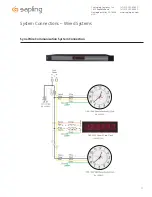
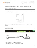
Inputs – GPS Installation
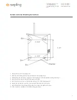
GPS Antenna Installation
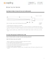
Supplied by Sapling: GPS Dome, a 75’ of RG58 or 150’ length of RG59 cabling (refer to Figure 1.1)
Not supplied by Sapling: Steel or PVC piping with 1”-14” thread or 3/4” pipe thread, teflon tape, mounting plate and hardware for piping (refer to
Figure 1.1)
*NOTE: Placement of antenna and height of piping needs to be on the rooftop of the building
1) Route cabling from the room in which the master clock will be located to the roof of the building, allowing the GPS dome (refer to Figure 1.1) to
have a full 180 degrees view of the sky
2) Run cabling through piping and attach the end of the cabling to the bottom of the GPS dome via TNC connection.
3) Screw GPS dome onto the top of the piping. Be careful not to twist the cable. Use teflon tape on the pipe threads to tighten seal and prevent
water damage.
4) Mount piping to the roof of the building with mounting plate and hardwear supplied by the user.
5) Connect the RG58 or 59 cabling to the GPS input located on the back of the master clock via NTP connection.
Setting Master Clock to GPS Mode
P
rogramming through the NTP 7000 push buttons
- Refer to page 22 for setting your master clock’s time source to GPS from the LCD display.
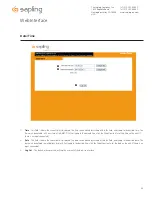
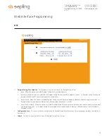
Programming through the Web Interface -
Refer to page 31 for setting your master clock’s time source to GPS from the web interface.
Fig 1.1
GPS Dome
Piping
Mounting Plate
TNC Connection
NTP Server
Connection


