


-
9
-
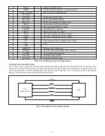
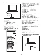
Fig. 5-1 Internal Bus Communication System
2. Internal Communication Bus
The SYA block carries out overall control of camera operation by detecting the input from the keyboard and the condition of the
camera circuits. The 8-bit microprocessor reads the signals from each sensor element as input data and outputs this data to the
camera circuits (ASIC) or to the LCD display device as operation mode setting data. Fig. 5-1 shows the internal communication
between the 8-bit microprocessor, ASIC and SPARC lite circuits.
Table 5-1. 8-bit Microprocessor Port Specification
-
ZAVJACK
AV JACK connection detection (AD conversion)
VSS1
UNREGSY
Camera power voltage input
CF2
Open
VDD1
-
KEY_2ND
Key input 2nd SHUTTER (L= input)
ZUSBDET
USB detection (L= detection)
RESET
Microcomputer reset (L= reset)
XCIN
Sub-clock oscillation terminal (32.768kHz)
XCOUT
Sub-clock oscillation terminal (32.768kHz)
CF1
VDD connection built-in oscillation circuit : 4MHz
8-bit
Microprocessor
ASIC
SREQ
ASIC SO
ASIC SI
SCK
MRST
ZBAT_OFF
NOT USED
HOTLINE
BAT_TEMP
-
Hot line request from ASIC
Battery temperature detection
Battery OFF detection (L= battery OFF)
Serial communication request signal
ZSREQ
HINGE
LCD panel rotation detection (L= panel inversion)
ZBOOT_COMREQ
TH_TEMP
Camera temperature detection
ASIC_SDI
Serial data output to ASIC
ASIC_SDO
Serial data input from ASIC
PLLEN
43
44
45
46
47
48
49
50
51
52
53
54
55
56
57
58
59
60
61
62
63
64
O
I
I
-
I
I
I
I
I
I
I
I
I
-
I
I
-
I
I
I
O
I
PLLEN
ASIC PLL ON/OFF control
BOOT output and COMREQ input
Summary of Contents for VPC-CG11EXG
Page 11: ... 11 MEMO ...
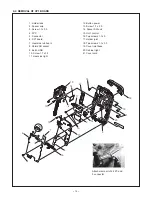
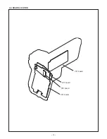
Page 16: ... 16 2 4 BOARD LOCATION VF1 board ST1 board TB1 board CP1 board ...
Page 25: ...25 1 5 4 2 3 6 7 ...
Page 58: ...Aug 09 SANYO Electric Co Ltd Osaka Japan ...
Page 59: ...SIEMENS STAR CHART ...


