background image

– 7 –

ADJUSTMENT
 ITEM

TIMING
PATTERN

SETTING

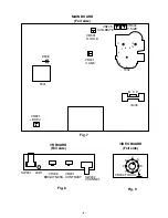
VR
LOCATION

ADJUSTMENT  PROCEDURE

HORIZONTAL
HOLD AD-
JUSTMENT

VERTICAL
SIZE ADJUST-
MENT

HORIZONTAL
WIDTH  AD-
JUSTMENT

VERTICAL
LINEARITY
ADJUSTMENT

FOCUS
ADJUSTMENT

RASTER
CENTERING
ADJUSTMENT

RASTER TILT
ADJUSTMENT

BRIGHTNESS
ADJUSTMENT

VERTICAL
HOLD AD-
JUSTMENT

PATTERN GENERATOR
MODE CROSS-HATCHED
PATTERN

PATTERN GENERATOR
MODE MONOSCPE
PATTERN

PATTERN GENERATOR
MODE MONOSCPE
PATTERN

PATTERN GENERATOR
MODE CROSS-HATCHED
PATTERN

PATTERN GENERATOR
MODE DOT PATTERN

DISCONNECT VIDEO
SIGNAL

PATTERN GENERATOR
MODE CROSS-HATCHED
PATTERN

DISCONNECT VIDEO
SIGNAL

PATTERN GENERATOR
MODE MONOSCPE
PATTERN

This adjustment is required only if display
moniter has a H-HOLD problem .
Adjust H-HOLD VR301 until the pattern is
stable hold.

Adjust VR402 until height for eye comfort
obtained.

Adjust VR901 until D908(+) voltage to
114V to 115V (at 110V AC),113.5V to
114.5V (at 120V AC).

Adjust the vertical linearity control VR401
for equal spaceing of lines between the
center extreme of scan.

The focus control may be adjusted for
optimun focus by VR202.

The raster is centered by rotating the two
small at the rear of the yoke.

Loosen the screw on the rear of deflection
yoke, rotating the yoke to correct position
tighten the screw.

Adjust VR205 to the suitable brightness.

The vertical hold is automatic stop rolling.

VR301

VR402

VR901

VR401

VR202

VR205

2. SERVICE ADJUSTMENTS

CONTRAST VR
AND BRIGHT
VR TO CENTER.

CONTRAST VR
AND BRIGHT
VR TO CENTER.

CONTRAST VR
AND BRIGHT
VR TO CENTER.

CONTRAST VR
AND BRIGHT
VR TO CENTER.

CONTRAST VR
AND BRIGHT
VR TO CENTER.

CONTRAST VR
AND BRIGHT
VR TO CENTER.

CONTRAST VR
AND BRIGHT
VR TO CENTER.

CONTRAST VR
AND BRIGHT
VR TO MAX.

CONTRAST VR
AND BRIGHT
VR TO CENTER.

Summary of Contents for VM-6619A

Page 1: ...gs 3 Before returning the set to the customer always perform an AC leakage current check on the exposed metallic parts of the cabinet such as terminals screwheads metal over lays etc to be sure that the set is safe to operate without the danger of electrical shock Plug the AC line cord directly into a 120 V AC outlet Do not use a line isolation trans former during this check Use an AC voltmeter wi...

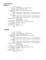
Page 2: ... control Termination switch Operating environment Power source Power consumption Dimension W x H x D Weight CCIR standard 20 measured diagonally 90 deflection angle More than 1000 TV lines center Horizontal 15 625 kHz CCIR Vertical 50 Hz CCIR Composite video 1 line BNC connector 1 0 V p p 75 ohm negative sync Composite video 1 line BNC connector 1 0 V p p 75 ohm negative sync Composite video 1 lin...

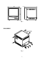
Page 3: ... 4 Fig 1 W D H Fig 1 DISASSEMBLY 1 1 1 1 1 1 2 1 2 1 METAL TOP COVER ...

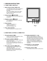
Page 4: ...his socket and to a wall outlet 2 Video input terminals VIDEO IN These terminals are used to input a video signal source to this monitor Connect to the video output of a VCR or an other monitor for loop through connection or to a video camera 3 Video output terminals VIDEO OUT These terminals are used to output a video signal from this monitor Loop through output of the video in BNC connector then...

Page 5: ... Video B INPUT terminal Video signal cable To Video A INPUT terminal Video signal cable Rear panel To Video input terminal To Video input terminal Monitor Video recorder Fig 3 Monitor Video recorder To Video input terminal Coaxial cable Video camera Fig 5 1 2 3 4 7 6 ...

Page 6: ...stable hold Adjust VR402 until height for eye comfort obtained Adjust VR901 until D908 voltage to 114V to 115V at 110V AC 113 5V to 114 5V at 120V AC Adjust the vertical linearity control VR401 for equal spaceing of lines between the center extreme of scan The focus control may be adjusted for optimun focus by VR202 The raster is centered by rotating the two small at the rear of the yoke Loosen th...

Page 7: ...8 7 6 5 4 3 2 1 VR202 FOCUS 2 1 3 4 5 6 7 8 VIDEO BOARD MAIN BOARD VR406 SW901 LED1 VR201 SW202 VR BOARD 11 12 BRIGHTNESS CONTRAST CHANNEL B ADJ H HOLD V LINE V SIZE SUB BRITE D908 Fig 7 Fig 8 MAIN BOARD Foil side VR BOARD Foil side VIDEO BOARD Foil side Fig 9 ...

Reviews: