


PARTS NAMES AND FUNCTIONS
1
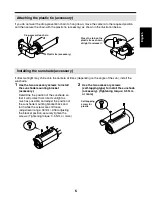
Camera mount (See p5)
Used to install the camera to a wall or ceiling
with mounting screws (M8x4, sold
separately).
2
Camera position adjustment screws
(See p5)
You can use the hexagonal wrench (large,
accessory) to loosen these screws and then
adjust the direction of the camera. There are
four screws on the camera mount, four on
the camera itself and two on the arm section.
3
Camera fixing base (See p43)
4
Menu setting plate (See p11)
The camera can be set using menu
operations.
In addition, a monitor (sold separately) for
checking operation can be attached
temporarily.
5
L-shaped camera fixing bracket (See p43)
6
Sunshade mounting bracket screw holes
(See p6)
Use the sunshade mounting bracket screws
(2, accessories) to install the sunshade.
7
Camera cover fixing screws
If you use a Phillips screwdriver to loosen
these four screws, you can then remove the
camera cover.
There is no need to remove the camera
cover except when using the menu setting
plate
4
or during maintenance.
If the camera cover has been removed,
tighten these screws to 0.5 N.m or more
when reinstalling it in order to ensure
watertightness.
CAUTION:
The camera cover will come off if the camera
cover fixing screws are loosened by about 5
mm, so be careful not to loosen them too
much. If a screw is loosened too much, the
drop-prevention washer inside the cover may
come off and the screw may fall out.
2
1
H
Color display label
Camera cover
One-touch connector
F
G
8
7
6
4
3
5
9
GND
SET
MONITOR
CURSOR
CURSOR button
SET button
MONITOR
(Monitor terminal)
GND
(Ground terminal)
Eng
lis
h
3
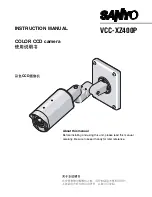
Summary of Contents for VCC-XZ400P
Page 46: ......


