background image

Click 

PAN/TILT

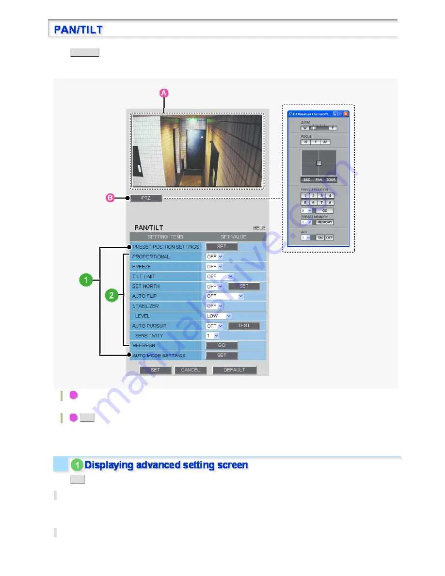
 button in the configuration menu to display the PAN/TILT screen.

On this screen, you can configure the detailed settings of the preset positions or the auto mode, as well as the 

optional functions for panning/tilting.

A

Live video:

You can confirm the orientation of the camera lens and the zoom conditions or other functions.

B

PTZ

 button:

Click this button to display the PTZ controller.

You can use the control panel in the same manner as that on the live video screen.

Click 

SET

 to display the advanced setting screen.

PRESET POSITION SETTINGS

You can register the camera lens orientation, focus and zoom conditions, and other conditions as a preset 
position. Up to 255 preset positions can be registered.

AUTO MODE SETTINGS

You can configure four automatic mode operations: sequence, automatic panning, tour and automatic return.

Working with Administrator Configuration Screens 41/77

Summary of Contents for VCC-HD5600 series

Page 1: ...VCC HD5600 HD5600P series Features of This Camera Specifications Target size and recording time Power Unit Connection and Settings Introduction1 14 ...

Page 2: ...era lens orientation with your PC mouse With a 10 built in optical zoom lens the camera offers a zoom magnification of up to 160 in conjunction with the electronic zoom function By installing an SD memory card or external hard disk sold separately surveillance video can be recorded on the camera side The camera s motion sensor function can work in conjunction with any external alarm device facilit...

Page 3: ...adjustable indoor outdoor fluorescent Backlight compensation Multi spot evaluative metering center weighted evaluative metering masking face detection Electronic sensitivity boosting Auto 32 max or Off Electronic shutter VCC HD5600P 1 25 1 50 1 120 1 250 1 500 1 1000 1 2000 1 4000 1 10000 VCC HD5600 1 30 1 60 1 100 1 250 1 500 1 1000 1 2000 1 4000 1 10000 Long exposure shutter 1 2 4 8 16 32 Iris A...

Page 4: ...recording in event of a network failure log information External HDD Normal recording alarm recording backup video recording in event of a network failure log information Network Image video compression H 264 JPEG Video size H 264 16 9 1920 1080 1280 720 640 360 320 180 4 3 1600 1200 1280 960 1024 768 640 480 320 240 Video size JPEG 16 9 1920 1080 1280 720 1024 576 640 360 4 3 1600 1200 1280 960 1...

Page 5: ...mensions Unit mm inch A Camera unit approx 1 3 kg 45 9 oz B Power unit Approx 450 g 15 9 oz C Surface cover approx 110 g 3 9 oz Appearance and specifications are subject to change without prior notice or obligations Introduction 5 14 ...

Page 6: ...n the PDF manual Refer to the table Target size and recording time in the electronic manual This table is displayed using a browser specific function and therefore not displayed on the PDF manual Refer to the table Target size and recording time in the electronic manual Introduction 6 14 ...

Page 7: ... please refer to Connection and Control Address Setting This is the connection point between the camera unit and the power unit A Control switch transmission rate and protocol setting etc B Address switch camera control address setting C Control terminal connection of controller and alarm input output cable Top A LAN terminal RJ 45 type Use this socket to connect the camera to your PC to enable ne...

Page 8: ... video and sound Connect this terminal to a monitor etc A live video will be displayed on the monitor once the camera is turned on By installing an HDMI option board VA HDB90 sold separately the camera can be connected to a high vision monitor Perform the following connections according to the installation environment and application of your camera A Power Connection B Network Connection C Control...

Page 9: ...nected to the GND earth grounding terminal To prevent a fire hazard use any UL listed wire rated VW 1 Be sure to use an 18AWG or thicker wire power cable 230 VAC Type Please refer to the instruction manual that came with the product This camera is designed so that you can use all of its functions via network operation By connecting the network LAN socket of the camera to your PC using a LAN cable ...

Page 10: ...efer to your router s Instruction manual To connect two or more cameras on the NETWORK SETTINGS screen assign them with port numbers that are different from that of the first camera Connect the alarm input output cable and controller to the control terminal of the interface board Use a thicker cable than 24AWG for connection Maximum length 600 m Installing and removing the interface board To place...

Page 11: ...INGS screen When using the alarm input terminal for day night switching configure the following settings Under DAY NIGHT set DAY NIGHT to COLOR and select the terminal you want to use in EXT ALARM On the ALARM SETTINGS screen in POLARITY select the signal polarity of the alarm input terminal Connecting an external switch to ALARM IN1 allows you to set the system clock by operating the switch To se...

Page 12: ...2 Inserting an SD Memory Card Insert the SD card into the slot until it is locked with a clicking sound Push the SD card a bit further into the slot to eject it When you insert a new recording medium format it on the SD HDD screen When you remove the recording medium first set SD MEMORY CARD HDD on the SD HDD screen to NO USE When you connect the camera to a controller it is necessary to configure...

Page 13: ...inator When you connect multiple cameras set the terminator setting Switch 6 of the final device to ON and all other devices to OFF When you connect multiple cameras allocate a unique RS485 protocol address camera number to each camera Configure the address by setting the dip switches to ON and OFF Configure the switches according to the List of Address Configuration Switches shown below Circles i...

Page 14: ...List of Address Configuration Switches Introduction 14 14 ...

Page 15: ... HD4600P From Connection to Network Operation Live Video Monitoring Alarm Detection and Output Recording Surveillance Video Software Information Configuration menu quick reference tables Quick Operation Guide1 14 ...

Page 16: ...d MONITOR OUT terminals simultaneously Set the preferred output terminal under TV OUT on the VIDEO AUDIO SETTINGS screen 3 Connect the network LAN socket to your PC using a LAN cable Check the operating environment of your PC and perform the following operations Check the network information on your PC Install the H 264 Plug in from the supplied CD ROM onto your PC 4 Connect a microphone and a spe...

Page 17: ...ople of the occurrence of an alarm condition 6 Install the recording medium After installation the medium requires to be formatted 1 SD memory card Insert it into the SD card slot 2 External hard disk Connect the drive to the EX HDD terminal 7 Turn on the camera The power indicator lights up and live video appears on the monitor 8 Access the camera from your PC s Web browser Live video appears on ...

Page 18: ...M1 and STREAM2 are as shown in the screenshots below ADD Use this button to add up to two custom stream patterns STREAM3 and STREAM4 CHANGE Use this button to change stream settings STREAM1 to STREAM4 DELETE Use this button to delete registered stream patterns Digital PTZ Function The digital PTZ function lets you clip specific areas of the subject in VGA size and perform zoom pan and tilt operati...

Page 19: ...spect ratio Audio condition configuration In MIC SENSITIVITY select the microphone sensitivity In FILTER 500Hz enable or disable the audio filter In OUTPUT LEVEL select the desired audio output level Audio output configuration Set AUDIO CAMERA TO PC to ON on the CLIENT SETTINGS screen Audio input configuration Set AUDIO PC TO CAMERA to ON on the CLIENT SETTINGS screen Quick Operation Guide 5 14 ...

Page 20: ...ra to detect alarm conditions such as entry of an intruder Setting Item Default Setting Optional Setting ALARM IN1 2 Alarm input terminal number OFF Disables alarm detection ON Enables alarm detection POLARITY Signal polarity NO Ex Detects an alarm when door is closed NC Ex Detects an alarm when door is opened ACTION action the camera makes when an alarm condition is detected OFF No action ZOOM Zo...

Page 21: ...n in masked areas B Detecting motion in specific areas C Detecting motion with lines and areas drawn on the screen In MOTION after selecting a motion sensor type click DETAIL to configure the detection conditions on the detailed configuration screen You can configure the camera to automatically output alarm signals or remotely manually output alarm signals You can configure the camera to automatic...

Page 22: ... terminal receives an alarm signal MOTION Output condition OFF Disables alarm output using motion sensor ON Triggers alarm output using motion sensor Use the Remote Alarm buttons provided on the live screen to send alarm signals from the camera s alarm output terminals Setting Item Default Setting Optional Setting ALARM OUT1 2 Alarm output terminal number OFF Disables alarm output REMOTE Enables r...

Page 23: ...pplied downloader software HDC Downloader and playback software DLViewer to play back the video on the PC 1 Click SD HDD in the configuration menu On the SD HDD screen you can format the recording media Setting Item Default Setting Required Setting Operation 1 SD MEMORY CARD HDD NO USE USE Use the media for recording 2 AREA Ratio of the recording areas NORMAL 80 Normal recording storage area ALARM...

Page 24: ... FAILURE 6 PRE ALARM OFF ON Records video for a specific period before alarm occurrence 7 REC BUTTON OFF ON Records video using the emergency recording button on the live screen control panel When finished configuring the above basic recording settings configure the recording schedule as required 3 On the RECORDING screen click SCHEDULE Setting Item Default Setting Required Setting 1 SCHEDULE OFF ...

Page 25: ... make the maximum use of this camera we recommend that you use this application You can record JPEG images only You need to configure recording and other conditions on the application s configuration screens Recording video to an FTP server To record video by sending image data from the camera to an FTP server you need to configure the image transmission conditions on the FTP SETTINGS screen You c...

Page 26: ...pplication for monitoring live video from more than one camera This monitoring application is designed for use with SANYO network cameras You can access up to 128 cameras simultaneously The application lets you monitor video images from connected cameras in either the single screen or the 4 screen 9 screen or 16 split screen mode E Auto IP Setup Utility for automatically setting up IP addresses wh...

Page 27: ...een Menu Registering new users USER REGISTRATION Changing the password user name and operation privilege of users Allowing all users to access the camera without any authentication check Restricting PCs that have access to the camera SECURITY SETTINGS Configuration Related to Live Video Operation Configuration Screen Menu Accessing the camera from video viewer or similar software to view live vide...

Page 28: ...the latest version OPTION SETTINGS FIRMWARE UPDATE Restoring the factory default settings OPTION SETTINGS FACTORY DEFAULT Backing up or uploading settings OPTION SETTINGS MENU BACKUP MENU UPLOAD Viewing the access log system log and operation log OPTION SETTINGS LOG Quick Operation Guide 14 14 ...

Page 29: ...VCC HD5600 HD5600P series Access the camera from your Web browser Live Screen Components Control panel Tool panel Information bar Working with Live Screen1 18 ...

Page 30: ...default IP address will fail if that address is already being used by another device in the network If so change the IP address of the existing device before accessing the camera 3 Type your user name and password and click OK The language selection screen appears When you access the camera for the first time login as an admin user and perform the necessary configurations User name and password de...

Page 31: ...aneously use the following software Monitoring software VA SW3050Lite Supplied Installing this software adds to your PC the capability to simultaneously access two or more cameras and monitor live video from all connected cameras on a multi view screen Recording software VA SW3050Server Client Optional This software is higher grade software than VA SW3050Lite that adds recording and playback capab...

Page 32: ...OCK SETTINGS screen You may change the date time format month day year year month day or day month year clock type character size and display position on the CLOCK SETTINGS screen 2 Zoom magnification The current zoom magnification is displayed 3 Video image display Shows JPEG images or H 264 video To change the video image stream displayed on the live screen click CLIENT SETTINGS on the control p...

Page 33: ...Image centering operation Clicking the video image changes the camera s orientation so that the point where you click is located at the center of the image Working with Live Screen 5 18 ...

Page 34: ...lt zoom and move to preset positions etc B CLIENT SETTINGS Click this to select the live stream and streaming protocol for each user C MENU Click this to display the configuration menu D LANGUAGE Click this to display the language selection screen E DISPLAY Click this to display the image size adjustment panel Required operation privilege admin operator1 operator2 Working with Live Screen 6 18 ...

Page 35: ...zoom magnification 2x 4x 8x 16x Click the buttons to adjust the focus NEAR Focus on a near object FAR Focus on a distant object AUTO FOCUS Automatic focus The camera lens orientation can be changed by dragging or clicking the mouse on the screen Drag operation Operate as though using a joy stick for pan tilt operation on the system controller Drag the central cursor horizontally to pan and vertica...

Page 36: ...O MODE SETTINGS screen is conducted PRESET MEMORY Select the registration number 1 to 255 from the pull down menu and click MEMORY The current camera lens orientation zoom magnification and focus are registered The preset position can also be registered in the PRESET POSITION SETTINGS screen PRESET POSITION Specify the preset position registration number and click GO The camera lens orientation zo...

Page 37: ...A RTSP LOCAL AREA RECORDING HTTP INTERNET MULTICAST Click SET to save the settings To close the screen without saving the settings click CLOSE This camera supports bidirectional audio communications so you can send and receive audio between the camera and your PC Hearing sounds from camera Sending audio messages to camera To perform bidirectional audio communications for both the camera and your P...

Page 38: ... can send audio alerts to suspicious people or communicate with people at the camera Required operation privilege admin operator1 operator2 Only a single user per camera may send audio messages at a time If two or more users send audio simultaneously the user who sends last will take precedence 1 Click CLIENT SETTINGS on the control panel The CLIENT SETTINGS screen appears 2 Set AUDIO PC TO CAMERA...

Page 39: ...control panel to display the configuration menu that includes a series of menu selection buttons Clicking one of these menu selection buttons displays the corresponding configuration screen If you are a surveillance system administrator use these buttons to configure necessary settings according to the installation environment and application of your camera Required operation privilege admin opera...

Page 40: ...D SD HDD Format the SD memory card or external hard disk 10 E MAIL E MAIL SETTINGS Configure the alarm notification e mail function and other automatic transmission settings 11 FTP FTP SETTINGS Configure the image streaming conditions if you intend to record images from the camera to an FTP server 12 SECURITY SECURITY SETTINGS Configure the security settings for permitting or rejecting the access ...

Page 41: ...ize adjustment panel Panel is minimized Clicking the button opens the panel Clicking the button closes the panel SIZE The available options vary depending on your selections in ASPECT RATIO and CODEC JPEG 16 9 1920 1080 1280 720 1024 576 640 360 JPEG 4 3 1600 1200 1280 960 1024 768 800 600 640 480 320 240 H 264 16 9 1920 1080 1280 720 640 360 320 180 H 264 4 3 1600 1200 1280 960 1024 768 640 480 3...

Page 42: ...he screen Clicking the button again restores the normal screen Click this button to capture the desired scene of the JPEG live streaming as a still image in a separate window You can then save and print the captured image For details refer to the Printing and Saving a Still Image section Click this button to send audio messages from the PC to camera For details refer to the Configuring audio secti...

Page 43: ...ow You can capture and then save or print the desired scene of the JPEG live streaming during monitoring 1 Click the Capture button on the tool panel The captured still image appears in a separate window JPEG images can also be printed saved while H 264 images are being displayed When a captured still image is shown the live screen continues to display moving images in the video display area 2 Rig...

Page 44: ...turns orange and an alarm signal is output from the corresponding terminal If the camera is connected to a buzzer or other external device you will hear an alarm sound from that device A Click this to send an alarm signal from the ALARM OUT1 terminal B Click this to send an alarm signal from the ALARM OUT2 terminal 2 Stopping alarm signal output The way you stop alarm signal output differs dependi...

Page 45: ...nd the DURATION recording time 1 Starting Recording Click the emergency recording button grey Recording begins and the button changes to orange 2 Stopping Recording The method of stopping varies according to the configuration of DURATION under REC BUTTON on the RECORDING screen Automatic Stop This is available in the case where recording time is configured in DURATION When the configured recording...

Page 46: ...r label causes system information to appear in a separate window The INFO status indicator appears in orange until either of the following conditions is met In case of an error The error condition is resolved In case of a warning The SYSTEM INFORMATION window opens 2 REC Recording in progress 3 ALARM An alarm signal received Working with Live Screen 18 18 ...

Page 47: ...CLOCK SETTINGS USER REGISTRATION VIDEO AUDIO SETTINGS CAMERA SETTINGS PAN TILT ALARM SETTINGS RECORDING SD HDD E MAIL SETTINGS FTP SETTINGS SECURITY SETTINGS SCHEDULE SETTINGS OPTION SETTINGS Working with Administrator Configuration Screens1 77 ...

Page 48: ...ress subnet mask and other information 1 In IP ADDRESS select FIX and type the IP address of the camera below it 2 In SUBNET MASK and GATEWAY type your subnet mask and gateway addresses respectively 3 In DNS PRIMARY and DNS SECONDARY type your primary and secondary DNS server addresses and click SET Because you selected FIX in IP ADDRESS you specify here fixed DNS server addresses After completing...

Page 49: ... reconnect to the camera to apply the changes Using SANYO s DDNS service you can connect to the camera from your Internet Explorer by simply entering the registered domain name instead of the IP address of the camera To use the DDNS service configure the following settings Specify your DNS server address under DNS SETTINGS on this screen Configure the port forwarding on your router For details ref...

Page 50: ...in name Follow the steps below to register your domain name 1 On the LOG IN screen enter the user name and password you wrote down and click Login The Domain Name registration change screen appears SANYO DDNS service site URL https www ddns sanyosecurity com 2 Enter the domain name you want to use and click Submit The domain name is registered with the DDNS server Working with Administrator Config...

Page 51: ...mmunication enables the encryption of image transmission SSL communication is effective for JPEG streaming images only When SSL communication is enabled you will be presented with a security warning dialog box when attempting to access the camera However this is not a problem and you can continue the operation by clicking Yes If the message This page contains both secure and nonsecure items appear...

Page 52: ...for each JPEG stream and click SET These settings are used for each stream for which you set the codec to JPEG on the VIDEO AUDIO SETTINGS screen An access name must be specified for each stream up to 32 alphanumeric characters 2 Under ACCESS NAME H 264 type an access name for each H 264 stream and click SET These settings are used for each stream for which you set the codec to H 264 on the VIDEO ...

Page 53: ... in the range of 1026 to 65534 that do not overlap with the unicast RTP port numbers except for numbers between 4000 and 5000 10000 10001 38214 and 49152 The multicast TTL must be specified in the range of 1 to 255 Working with Administrator Configuration Screens 7 77 ...

Page 54: ...ars on the live screen Note that the camera title cannot include the following symbols double quote single quote ampersand greater than sign percent backslash less than sign vertical bar and semicolon A warning dialog box will appear when you click SET if the camera title includes any invalid character 1 In CLOCK SET configure the current date and time in DATE and TIME respectively The configured ...

Page 55: ...y adjust the camera s internal clock OFF Disables the clock adjustment function ON NTP Enables automatic clock adjustment that retrieves the date and time information from the NTP server You need to configure the NTP settings LOGIN PC Enables automatic clock adjustment that retrieves the date and time information from the PC when an admin user logs into it ALARM IN1 Enables automatic clock adjustm...

Page 56: ...CLOCK ADJUST is selected the clock adjustment function adjusts the clock in the following timings When the camera is turned on At the time selected in TIME TO SYNCHRONIZE every day When any change is made to the settings on this screen To use a domain name you must specify the DNS server address in DNS SERVER ADDRESS on the NETWORK SETTINGS screen 1 In CLOCK ADJUST select ALARM IN1 2 In CLOCK IN s...

Page 57: ...ter up to 20 client users For a new user you can assign the same name as an existing user 1 Click ADD The USER REGISTRATION screen appears in a separate window A User list Displays the list of registered users This list initially shows the factory default users admin operator1 operator2 download and guest For these factory default users you can change the password only B ANONYMOUS USER LOG IN pull...

Page 58: ...ges section 5 In CLIENT SET select whether or not to allow the user to change the stream and password settings on the CLIENT SETTINGS screen and click SET The settings are saved and the USER REGISTRATION screen closes The user list now includes the user you just registered In STREAM SET specify whether to allow the user to change the live stream setting admin Does not allow the user to change the ...

Page 59: ...ow 2 Change the desired settings and click SET Your changes are saved and reflected in the user list Select the check box next to the user you want to delete and click DELETE The selected user is deleted from the user list You cannot delete the factory default users admin operator1 operator2 download and guest Working with Administrator Configuration Screens 13 77 ...

Page 60: ...stream configure RECORDING to ON and click SET If you configure to OFF you can only view the video streams and cannot record them Clicking SET reboots the camera This camera supports multi stream video transmission allowing you to register up to four video image streaming condition patterns Thus you can reduce the load of the entire system by choosing optimal settings for your application such as ...

Page 61: ...ter and click SET The settings are saved The stream list now includes the stream you just registered 1 In NAME type the stream name you want You can type up to 64 alphanumeric characters 2 In RECORDING select the recording type OFF NORMAL ALARM NORMAL ALARM NETWORK FAILURE The configured contents are reflected in RECORD STREAM on the RECORDING screen This cannot be configured if the recording conf...

Page 62: ...on in CODEC and your camera model JPEG VCC HD5600 0 1ips 0 2ips 0 5ips 1ips 3ips 5ips 10ips 15ips 30ips VCC HD5600P 0 1ips 0 2ips 0 5ips 1ips 2 5ips 5ips 8ips 12 5ips 25ips H 264 VCC HD5600 5ips 10ips 15ips 30ips VCC HD5600P 5ips 8ips 12 5ips 25ips 8 In PRIORITY select whether you put priority on the video image quality or the bit rate QUALITY BIT RATE If you selected QUALITY in PICTURE QUALITY sp...

Page 63: ...ed in the stream list 3 Click SET in the stream list The camera restarts and the changed settings are applied 1 Select the check box next to the stream you want to delete and click DELETE The selected stream is deleted from the stream list 2 Click SET in the stream list The camera restarts and the stream you selected has been deleted Configure the conditions of the audio you receive from the camer...

Page 64: ...the following 4 levels 2 1 0 1 If you have the HDMI optional board installed on the camera you need to configure the video output connector you want to use You cannot output video signal from the HDMI connector and the MONITOR OUT connector at the same time 1 In TERMINAL select the video connector you want to use AUTO A connected connector is detected automatically HDMI MONITOR OUT If both the HDM...

Page 65: ...f you select ON the zoom factor and the panning titling position are displayed on the monitor 4 In DISPLAY POSITION set the OSD display position and then click SET UP LEFT UP RIGHT DOWN LEFT DOWN RIGHT Working with Administrator Configuration Screens 19 77 ...

Page 66: ...Click one of the menu items in the sub menu to jump to the desired camera setting screen 2 DEFAULT Click this button to reset all the settings you configured for the selected view CAM1 CAM8 to the defaults factory settings 3 LENS INITIALIZATION Initialize the lens focus and zoom settings This area shows a series of camera settings You can use the vertical scroll bar and scroll buttons to scroll th...

Page 67: ...VIEW 8 APERTURE Corrects the profile of the target object VIEW 9 VIVID COLOR EFFECT Increases the saturation of images VIEW 10 GAMMA Adjusts the contrast and brightness level VIEW 11 DNR Reduces automatically the image noise in low illuminance conditions VIEW 12 FOCUS Configure the lens focus settings Common 13 ZOOM Configure the optical zoom speed electronic zoom and other zoom settings Common 14...

Page 68: ...ons camera views for each preset position Configure the lens iris according to the luminance level of the target object AUTO Selects the auto iris mode MANUAL Selects the manual iris mode The configured settings are applied only to the camera views that were specified in VIEW Configuring these settings enables the camera to automatically adjust the lens iris to reproduce natural images even in out...

Page 69: ...S select MANUAL 2 In EI enable or disable the electronic iris Adjusts the exposure controlling both the AGC circuit and the shutter speed OFF Disables the electronic iris ON Enables the electronic iris Enabling the electronic iris EI function causes the following The electronic shutter setting SHORT LONG will be cancelled and the electronic sensitivity boosting will not work Under extremely bright...

Page 70: ...SMART ATW select ON and click SET The camera now adjusts the white balance automatically based on the color information on the subject Enable the smart ATW function here because ATW may not produce desirable results if a single solid color occupies a large part of the subject Do not use the smart ATW function in environments where the color temperature fluctuates In an outdoor environment for exam...

Page 71: ...lance ATW does not reproduce a natural white balance AWC allows you to automatically adjust the white balance by simply clicking SET with the camera lens directed toward a white wall white paper and the like 1 In WHITE BALANCE select AWC 2 Direct the camera lens toward a white wall white paper and the like and in AWC LOCK click SET If the white balance adjustment does not reproduce desirable resul...

Page 72: ...to 255 dark BLUE 0 light to 255 dark You can use the backlight compensation BLC function to make the subject easily visible under strong backlight conditions OFF Disables the backlight compensation function MULTI Selects the multi spot evaluative metering mode CENTER Selects the center weighted evaluative metering mode MASKING Selects the light source masking mode FACE Selects the face detection b...

Page 73: ...ively Configure the position and size of the center metering area 1 In BLC select CENTER and click SET The BLC center window weighting setting screen appears showing a rectangle representing the center metering area in the center of the screen 2 Drag the rectangle to set the center metering area in position Center weighted average metering may not be set depending on the position of the center met...

Page 74: ...live video image from the camera 5 Click SET and then BACK The settings are saved and you return to the sub menu You can use light source masking to compensate for backlighting problems with human or other objects in the subject by masking the light source in a bright background 1 In BLC select MASKING and click SET The BLC masking screen appears 2 Drag the mouse over the live video image to selec...

Page 75: ...will not work even if any human face is detected AGC is set to OFF SHUTTER is set to SHORT or LONG IRIS is set to MANUAL Configure the electronic shutter according to the movement and luminance level of the target object OFF Disables the electronic shutter SHORT Enables the fast shutter mode LONG Enables the long exposure shutter mode The configured settings are applied only to the camera views th...

Page 76: ...ed 1 In SHUTTER select LONG 2 In SHUTTER SPEED select the desired shutter speed and click SET x1 x2 x4 x8 x16 x32 Each of the above shutter speed values represents a multiple of the field storage time The higher the value the longer the exposure time Setting an excessively long exposure time may result in ghosts blurs and white spots if the subject includes any moving object Configure the video si...

Page 77: ...ct OFF 2 In GAIN SETTING select the gain value of AGC and click SET 0dB 3dB 6dB 9dB 12dB 15dB 18dB 21dB 24dB 27dB 30dB 33dB 36dB 39dB 42dB The Day Night function improves the camera s sensitivity by automatically switching the camera to the color mode in bright conditions and to the black and white mode in dark situations Using this function enables 24 hour surveillance with clear video images eve...

Page 78: ...OFF 2 In LEVEL select the luminance level at which the video mode is switched and click SET HIGH Sets a high luminance level to increase the time during which the camera operates in the black and white mode MIDDLE Sets the luminance level to halfway between LOW and HIGH LOW Sets a low luminance level to increase the time during which the camera operates in the color mode ADJ Enables the manual adj...

Page 79: ...control signal is received 1 In DAY NIGHT select COLOR 2 In EXT ALARM select the desired alarm input terminal and click SET ALARM IN1 Sets the ALARM IN1 terminal as the Day Night switching terminal ALARM IN2 OFF Sets the ALARM IN2 terminal as the Day Night switching terminal Fixing Camera to Color Video Mode You need to enable the ALARM IN1 2 terminal and configure the signal polarity in POLARITY ...

Page 80: ...e the whole video image clearer Select ON in APERTURE and an appropriate correction level in LEVEL and click SET The higher the correction level the greater the correction effect 1 to 15 The configured settings are applied only to the camera views that were specified in VIEW Use the color saturation compensation function to improve the vividness of the color In VIVID COLOR EFFECT select ON and cli...

Page 81: ... the target object Configure the DNR Digital Noise Reduction function to reduce noise at low conditions In DNR select ON and click SET The configured settings are applied only to the camera views that were specified in VIEW Enabling the DNR function may cause ghosts and blurs if the subject includes any moving object which results in low resolution Configure the auto or manual focusing mode AUTO S...

Page 82: ...FACE DETECTION enable or disable auto focusing in face detection Use this setting to specify whether or not to use the auto focus function when a human face is detected in the focusing area you selected in AREA OFF Disables auto focusing in face detection ON Enables auto focusing in face detection A human face may not be detected if obscured by a hat sunglasses or mask or if the monitoring angle i...

Page 83: ...tronic zoom magnification and other zoom settings The configured settings are applied in common to all the camera views 1 In SPEED select the optical zoom speed Available settings 1 2 3 and 4 fastest 2 In EL ZOOM select the electronic zoom magnification power The optical zoom provides a maximum magnification power of 10 If you need a zoom magnification of more than 10 use the electronic zoom OFF D...

Page 84: ... mode normal video H Flips the video horizontally V Flips the video vertically HV Flips the video vertically and horizontally The configured settings are applied in common to all the camera views Configure to turn ON or OFF the motion sensor function for each camera view If you do not have to detect the motion in subjects set MOTION to OFF In MOTION select either ON or OFF and click SET The config...

Page 85: ...rientation of the camera lens you can apply up to 32 mask patterns to anywhere within the whole monitored area eight spots at the maximum for a single screen To select a mask pattern just click on it The selected mask pattern is shown with a yellow green border To move a mask pattern select it and then drag the mouse To resize a mask pattern place the mouse pointer over its border and then drag th...

Page 86: ...In SEMI TRANSPARENT select whether to enable or disable the transparency of the mask pattern s OFF Disables transparency ON Enables transparency 9 Click SET and then BACK The settings are saved and you return to the sub menu Working with Administrator Configuration Screens 40 77 ...

Page 87: ...button Click this button to display the PTZ controller You can use the control panel in the same manner as that on the live video screen Click SET to display the advanced setting screen PRESET POSITION SETTINGS You can register the camera lens orientation focus and zoom conditions and other conditions as a preset position Up to 255 preset positions can be registered AUTO MODE SETTINGS You can conf...

Page 88: ...s set beyond the limit angle you have just applied the camera will stop tilting at the point of the limit angle Use this feature if the bearing information is required to properly install the camera You can set zero degrees North to any direction 1 Use the PZT controller to move the camera lens to the direction you want to set as the reference bearing 2 Select ON for SET NORTH and click SET 3 Clic...

Page 89: ...otion sensor click the button The automatic pursuit function will not work in the following conditions The camera is moving in the automatic mode or by means of the preset function The camera is panning or tilting through manual operation Click GO to cleanse the contact point of the rotating section Once the cleaning is finished the system will perform the initializing operation Periodical cleanin...

Page 90: ...umeric characters can be used B The pause period at a preset position during the sequential operation TIME 3SEC 4SEC 5SEC 6SEC 7SEC 8SEC 9SEC 10SEC 15SEC 20SEC 30SEC 45SEC 1MIN C Monitoring conditions at a preset position VIEW 1 8 Select any from among up to eight patterns of monitoring conditions camera views which you set on the CAMERA SETTINGS screen OFF Currently used monitoring condition will...

Page 91: ... factory default setting Click SET in AUTO MODE SETTINGS on the PAN TILT screen to display the AUTO MODE SETTINGS screen On this screen you can configure four automatic mode operations as follows A Moving in a sequential manner among multiple preset positions SEQUENCE B Reciprocating between two preset positions specified AUTO PAN C Repeating a registered continuous operation pattern TOUR D Automa...

Page 92: ...slow to 15 quick Now the settings for the sequence 1 have been stored You can follow the same steps to configure for the sequences 2 to 4 Running the Stored Sequence Operation In SEQUENCE select a stored number and click RUN to close the menu screen and run a specified operation Four patterns of auto panning operation are available as shown below 1 Click PTZ to view the PTZ controller 2 Select 1 f...

Page 93: ...art point with specified tilt focus and zoom conditions Auto focus works only when the camera moves slowly or it pauses at the end point for more than five seconds You can configure up to four patterns of sequential operations such as panning tilting and zooming 1 Click PTZ to view the PTZ controller 2 Select 1 for TOUR 3 Click START and then YES in the confirmation dialog box The system starts re...

Page 94: ... to return to OFF Disables the auto return function SEQ1 4 Sequential operation 1 4 PAN1 4 Auto panning operation 1 4 TOUR1 4 Tour operation 1 4 PRESET Moves to a specified preset position Specify a number for PRESET NUMBER PREVIOUS Returns to the previous monitoring condition 2 Set a time period the system waits before it performs auto return and click SET 10SEC 20SEC 30SEC 40SEC 50SEC 1MIN 2MIN ...

Page 95: ...alarm input cable for the camera For details refer to the Control Terminal Connections section 1 Select 1 for the ALARM IN number ALARM IN NUMBER 1 8 2 Enable the settings select ON ALARM 3 In POLARITY select the signal polarity of the alarm input terminal NO Normally Open The terminal is normally open and closes when an alarm signal is received NC Normally Closed The terminal is normally closed a...

Page 96: ...k place when the alarm duration DURATION expires If another alarm input is received during the time specified in the DURATION setting an action will be made according to the last alarm received If the system is powered off while an alarm action is taking place it will restart in either of the following modes when turned on When RETURN is set to ON Restarts to perform the previous operating conditi...

Page 97: ...eset to the factory default value if you change any setting on the ALARM SETTINGS screen while an alarm state is retained To switch the alarm detection method in MOTION ALARM click the desired radio button 3 Click PTZ to view the PTZ controller 4 Use the controller to adjust the orientation of the camera lens while monitoring live video displayed on the monitor 5 Drag the mouse over live video ima...

Page 98: ...ject includes any intruder by detecting his her face If a human face is detected in the detection area when motion is detected the motion sensor will send a motion alarm A human face may not be detected if obscured by a hat sunglasses or mask or if the monitoring angle is not appropriate Checking how the motion sensor works Click TEST 2 If any motion is detected in a grid cell in the detection are...

Page 99: ... even if the motion is instantaneous The configured duration value will be reset to the factory default value if you change any setting on the ALARM SETTINGS screen while an alarm state is retained To switch the alarm detection method in MOTION ALARM click the desired radio button 3 Selects numbers for the stream and the preset position you want to detect You can select a preset position from 1 to...

Page 100: ...dio button to select a line or area number and specify detection conditions To delete a detection line or area click the LINE or AREA radio button to select a line or area number and click DELETE Example Configuring detection conditions for LINE 1 1 Select the LINE radio button and in the pull down menu select the line number 1 2 In SIZE select the size of the object you want to detect Specify the...

Page 101: ... the sensitivity 1 to 9 5 Click TEST to check how the motion sensor works with the current settings If any motion is detected with respect to the detection line or detection area that line will be shown in red Correct the detection conditions as required While the sensor is working this button is labeled as END To finish checking the motion sensor click the button During the test you cannot change...

Page 102: ...GER 4 Under TRIGGER configure the following alarm output conditions and click SET ALARM IN Specify the alarm input terminal to which the alarm input device is connected The ALARM OUT 1 terminal outputs an alarm signal when this terminal receives an alarm signal ALARM IN1 8 The terminal outputs an alarm signal via ALARM OUT1 when any of ALARM IN 1 to 8 receives an alarm signal MOTION You can config...

Page 103: ...n ALARM OUT TIME select how long you want the terminal to output the alarm signal and click SET The terminal will stop outputting the alarm signal when the set alarm output time expires 2SEC 5SEC 10SEC 15SEC 30SEC 45SEC 1MIN 2MIN 3MIN 4MIN 5MIN CC Stops outputting the alarm signal when the corresponding Remote Alarm button is clicked on the live screen To configure the ALARM OUT 2 to output an ala...

Page 104: ...igure the recording conditions in ALARM EVENT1 to ALARM EVENT4 step 4 NETWORK FAILURE If a network failure occurs during network recording backup recording is performed until the failure is resolved In NETWORK FAILURE TIME select the time from the occurrence of a network failure until the camera recognizes it as a recording trigger 15SEC 20SEC 30SEC 40SEC 50SEC 1MIN 2MIN 3MIN 4MIN 5MIN The setting...

Page 105: ... SETTINGS screen ALARM IN ALARM OUT1 2 The recording time depends on the ALARM OUT TIME setting on the ALARM SETTINGS screen ALARM OUT 3 In FRAME RATE set the frame rate of the post alarm video stream VCC HD5600 0 1ips 0 2ips 0 5ips 1ips 3ips 5ips 10ips 15ips 30ips VCC HD5600P 0 1ips 0 2ips 0 5ips 1ips 2 5ips 5ips 8ips 12 5 25ips Here you can select a frame rate slower than that set for the stream...

Page 106: ... surveillance video by clicking the emergency recording button on the live screen Here you can set recording duration and frame rate 1 Select ON for REC BUTTON If you select OFF the emergency recording button is not displayed on the live screen 2 Specify a recording time DURATION MANUAL Stops recording when the emergency recording button is pressed on the live screen 1MIN 2MIN 3MIN 4MIN 5MIN 10MIN...

Page 107: ...cord log information configure LOG to ON The log recording area is automatically configured so that approximately 16 000 access logs and 16 000 system logs can be stored respectively The recorded log information is retained even when the camera power is turned off 3 In AREA allocate the storage areas NORMAL 1 to 98 Recording area for normal video ALARM 1 to 98 Specify the recording area for alarm ...

Page 108: ...he recording area becomes full If recording stops because the recording area has become full you can turn OVERWRITE to ON or secure the recording space by deleting some recorded data to restart recording In AUTO DELETE enable or disable the auto delete function OFF 1DAY 2DAYS to 30DAYS Use the auto delete function to automatically delete recorded data that has been stored for a long period For exa...

Page 109: ...lt your network administrator 1 In E MAIL select ON to enable the e mail transmission function 2 In SSL select ON to use SSL communication If your e mail server supports SSL you can encrypt e mail transmission 3 Configure your e mail server Type the following information on your e mail server A SMTP SERVER ADDRESS Type the address of your SMTP server up to 64 alphanumeric characters B SMTP PORT NU...

Page 110: ...sk colon semicolon single quote double quote less than sign greater than sign broken bar 4 To send a warning e mail automatically in the event of a failure select the WARNING check box and click SET A warning e mail will be sent in any of the following cases When an SD card error occurrs When the remaining recording area is reduced to the warning level 20 10 When recording was stopped because the ...

Page 111: ...s an e mail when a specified ALARM OUT terminal outputs an alarm signal NETWORK FAILURE Sends an e mail when the camera detects a network failure during network recording A If you selected NETWORK FAILURE In NETWORK FAILURE TIME select the time from the occurrence of a network failure until the camera recognizes it as a recording trigger 15SEC 20SEC 30SEC 40SEC 50SEC 1MIN 2MIN 3MIN 4MIN 5MIN The s...

Page 112: ...l An e mail consists of the following portions Subject Camera Title Data and time Camera s IP address Message TEXT The camera title date and time IP address will be included automatically 1 In SUBJECT type the subject title of the e mail You can type up to 32 alphanumeric characters 2 In TEXT type the message text and click SET You can type up to 64 alphanumeric characters In the SUBJECT and TEXT ...

Page 113: ...mber is normally 21 default 3 In SERVER ADDRESS type the server address Then in USER ID and PASSWORD type the user ID and password respectively The number of characters you can type in these fields is as follows SERVER ADDRESS Up to 64 alphanumeric characters USER ID Up to 48 alphanumeric characters PASSWORD Up to 20 alphanumeric characters 4 To use the passive FTP mode in FTP PASSIVE select USE W...

Page 114: ... steps 5 to 6 the renamed file name will not include the date time and alarm factor information Both the temporary and permanent files will be overwritten if the same file name exists 1 In TRIGGER select the image transmission trigger condition The setting items you are required to configure are displayed in accordance with the selected trigger condition INTERVAL Sends a still image in fixed inter...

Page 115: ...cted ALARM IN1 8 MOTION ALARM OUT1 2 or NETWORK FAILURE only 1SEC 15MIN is displayed as an option In INTERVAL the pull down menu will only show options that do not exceed the DURATION setting 2 In JPEG IMAGE select the JPEG stream you want to send and click SET You can send JPEG images only You need to configure the video conditions for each stream on the VIDEO AUDIO SETTINGS screen The pull down ...

Page 116: ...er or not to grant it access to the camera You can configure the access settings for up to 10 PCs Individual access policy AUTHORIZED Permits access to the camera REJECTED Rejects access to the camera If there are duplicate address subnet mask settings one in the uppermost row is valid Example 1 When the global access policy DEFAULT POLICY is set to AUTHORIZED and the individual access policy is s...

Page 117: ...4 Click SET The settings are saved Working with Administrator Configuration Screens 71 77 ...

Page 118: ...r each day of the week Select the check box for the desired day of the week and in START and END specify the start and end time of the recording Example Configuring the camera to start recording at 1 00 and end recording at 19 00 every Sunday 18 hours Example 2 Select the desired day of the week and specify the start and end times of the recording If the end time is before the start time the syste...

Page 119: ... to click SET to update the schedule map If you change the scheduled settings while the schedule is enabled the camera will perform recording according to the changed schedule If you schedule overlapping recording periods the longer one will take precedence If the configured periods overlap as shown below they will be combined into one long period Follow the steps below to define your holidays 1 C...

Page 120: ... as an annual holiday in addition to weekly holidays Mondays defined in HOLIDAY 4 Click SET and then BACK The setting is saved and the HOLIDAY SETTINGS section disappears Working with Administrator Configuration Screens 74 77 ...

Page 121: ...SET to reboot the camera system You can update the camera s firmware to the latest version 1 Click SET The FIRMWARE UPDATE screen appears 2 Click BROWSE and select the firmware updater file 3 Click EXECUTE The firmware update process starts When the update process is completed the camera system reboots and you reconnect to the camera automatically Once you reconnect to the camera redisplay the OPT...

Page 122: ...onfirmation dialog box and specify the backup destination file All the settings on the NETWORK SETTINGS screen and the DATE TIME setting on the CLOCK SETTINGS screen are not saved You can restore the saved configuration settings of the camera from a backup file 1 In COPY RECORDING AREA SETTINGS select whether or not to restore the settings including the recording area settings WITH Includes the AR...

Page 123: ...ry card if necessary A ACCESS LOG Shows the history of access to the camera in chronological order up to 100 entries Date and time user name authentication check result OK NG connection destination IP address B SYSTEM LOG Shows a history of system operations and errors in chronological order up to 200 entries Working with Administrator Configuration Screens 77 77 ...

Page 124: ...VCC HD5600 HD5600P series Accessing the Camera Control Panel Tool Panel CAMERA SETTINGS Displaying LIVE video Transmitting Image Data Recording Pan Tilt Others Q A1 12 ...

Page 125: ...onnect the LAN cable 7 The switching hub is turned off Turn on the switching hub I cannot access the camera from within my home company network 1 The PC and camera IP addresses local addresses are configured with different subnet masks To use a PC and a camera within the same network their subnet masks must be the same Change settings so that the PC and camera have the same subnet mask 2 The Web b...

Page 126: ...h packet filtering or the like which restricts access from the Internet Change the settings in your router to allow access from the Internet For the configuration method refer to your router s instruction manual 5 The IP address you entered is a local address the one you use at your home When accessing via Internet enter the global address or the URL registered with the DDNS service and port numbe...

Page 127: ... have the operation privilege for the configuration screens Without the required operation privilege you will be presented with an authentication check dialog box when you click the MENU button on the live screen In this case you can change the operation privilege by entering a user name with an adequate operation privilege and its password in the dialog box The camera responds to neither focus no...

Page 128: ...settings if you have set SENSE UP in IRIS Set SENSE UP in IRIS to OFF I cannot turn off the AGC 1 You cannot set AGC to OFF when DAY NIGHT is set to AUTO Set DAY NIGHT to COLOR or B W 2 You cannot set AGC to OFF when SENSE UP in IRIS is set to ON Set SENSE UP in IRIS to OFF Q A 5 12 ...

Page 129: ...64 using HTTP or browse using JPEG I cannot install the H 264 Plug In included in the supplied CD ROM 1 The OS of your PC is not a recommended OS The OS must be Windows Vista Windows XP Home Edition or Windows XP Professional SP2 or later for the H 264 Plug In to run 2 You are not logged into the PC with administrator privileges To install the H 264 Plug In in a PC you need OS administrator privil...

Page 130: ...y 1 Among the multiple accesses to the camera some are from narrowband networks Change the minimum bit rate for video streaming to a large value 2 There are multiple accesses or accesses with request for multiple resolutions Increasing the number of accesses or simultaneous streamings with different resolutions may decrease the recording rate and or image quality Lower the resolution image quality...

Page 131: ...itored environment Alternatively in DAY NIGHT on the CAMERA SETTINGS screen select AUTO to enable the DAY NIGHT mode 2 The color quality for your PC monitor is configured to less than 16 bits On the Display Properties Settings tab configure the Color quality setting for your PC to 16 bits or more The image contains white spots or colored light spots You are using the camera in a dark place Or you ...

Page 132: ...tication setting according to the SMTP server setting This camera supports the two authentication methods SMTP and POP3 POP before SMTP 4 Transfer is blocked by the Outbound Port 25 Blocking OP25B implemented by your provider Select the SMTP authentication for the camera and change the destination e mail server port from 25 to 587 Use the destination e mail server of your provider Block e mail tra...

Page 133: ...ium for writing 5 The USB cable for the hard disk drive is not connected properly Turn off the HDD drive re insert the USB cable correctly and turn on the HDD drive again 6 An installed recording medium was removed before writing was stopped Format the recording medium If you remove a recording medium while writing is in progress you may damage it Be sure to perform the following procedure to stop...

Page 134: ... operation to correct position offset Wait for a while until the initialization completes A preset position loses accuracy The position of the camera lens might have been changed Initialize the lens by clicking LENS INITIALIZATION on the CAMERA SETTINGS screen or turn off the system and then turn it on to restart The camera lens stops at the vertical position facing ground during a tilt operation ...

Page 135: ...as the method for automatic time adjustment Select CLOCK and set CLOCK ADJUST to ON NTP 2 The NTP server address is not configured correctly Select CLOCK and configure the NTP SERVER ADDRESS settings again 3 The GATEWAY settings are not configured correctly Select NETWORK and configure the GATEWAY settings again The date and time information indicated on the live screen does not reflect the clock ...

Page 136: ...VCC HD5600 HD5600P series Copyright Notice How to use this manual Others1 8 ...

Page 137: ...r trademarks of their respective owners The SDHC Logo is a trademark The following license is applied to OpenSSL LICENSE ISSUES The OpenSSL toolkit stays under a dual license i e both the conditions of the OpenSSL License and the original SSLeay license apply to the toolkit See below for the actual license texts Actually both licenses are BSD style Open Source licenses In case of any license issue...

Page 138: ...PTION HOWEVER CAUSED AND ON ANY THEORY OF LIABILITY WHETHER IN CONTRACT STRICT LIABILITY OR TORT INCLUDING NEGLIGENCE OR OTHERWISE ARISING IN ANY WAY OUT OF THE USE OF THIS SOFTWARE EVEN IF ADVISED OF THE POSSIBILITY OF SUCH DAMAGE This product includes cryptographic software written by Eric Young eay cryptsoft com This product includes software written by Tim Hudson tjh cryptsoft com Original SSL...

Page 139: ...ive thereof from the apps directory application code you must include an acknowledgement This product includes software written by Tim Hudson tjh cryptsoft com THIS SOFTWARE IS PROVIDED BY ERIC YOUNG AS IS AND ANY EXPRESS OR IMPLIED WARRANTIES INCLUDING BUT NOT LIMITED TO THE IMPLIED WARRANTIES OF MERCHANTABILITY AND FITNESS FOR A PARTICULAR PURPOSE ARE DISCLAIMED IN NO EVENT SHALL THE AUTHOR OR C...

Page 140: ...the topic currently opened at the main window is highlighted so the current location among the manual can be easily confirmed 2 TITLE window This window shows the headline of the current topic This TITLE window never scrolls not to hide the headline 3 MAIN window This window shows the main detail contents Others 5 8 ...

Page 141: ...right of the TITLE window will display the previous page or the next page respectively 2 Page end is located at the end of the page This mark is also linked to the top of the page Click on this mark to jump to the top of the page Others 6 8 ...

Page 142: ...ettings that must be configured on other menu screens Caution Indicates prohibited or restricted operating and setting instructions This manual uses the following notations to present user interface related information Information such as the screen title is represented in all uppercase alphabetic letters as displayed on the screen Example NETWORK SETTINGS Information such as operation buttons and...

Page 143: ...losed in double quotes Example ON 80 Each section describing a configuration procedure begins with a screenshot of the corresponding initial configuration screen The purpose of this screenshot is to show you the factory default value for each setting item provided on the screen Others 8 8 ...

Reviews: