CONNECTIONS
Q
What you need
Peripheral equipment (such as monitor, digital video recorder or time-
lapse VCR)
Cables for connecting peripheral equipment and camera (coaxial cables,
connecting plugs)
Power adapter (24 V AC or 12 V DC)
Q
Supported coaxial cables
You can use any of the following coaxial cables:
RG-59U (3C-2V) Length: 250 m max.
RG-6U (5C-2V)
Length: 500 m max.
RG-11U (7C-2V) Length: 600 m max.
When using an RG-59U (3C-2V) cable, do not use it on piping or air
wiring.
Select the cable according to the distance between the devices you wish
to connect.
If you use a cable other than the types above, the image or sync signal
will be attenuated and will not be transmitted correctly.
Q
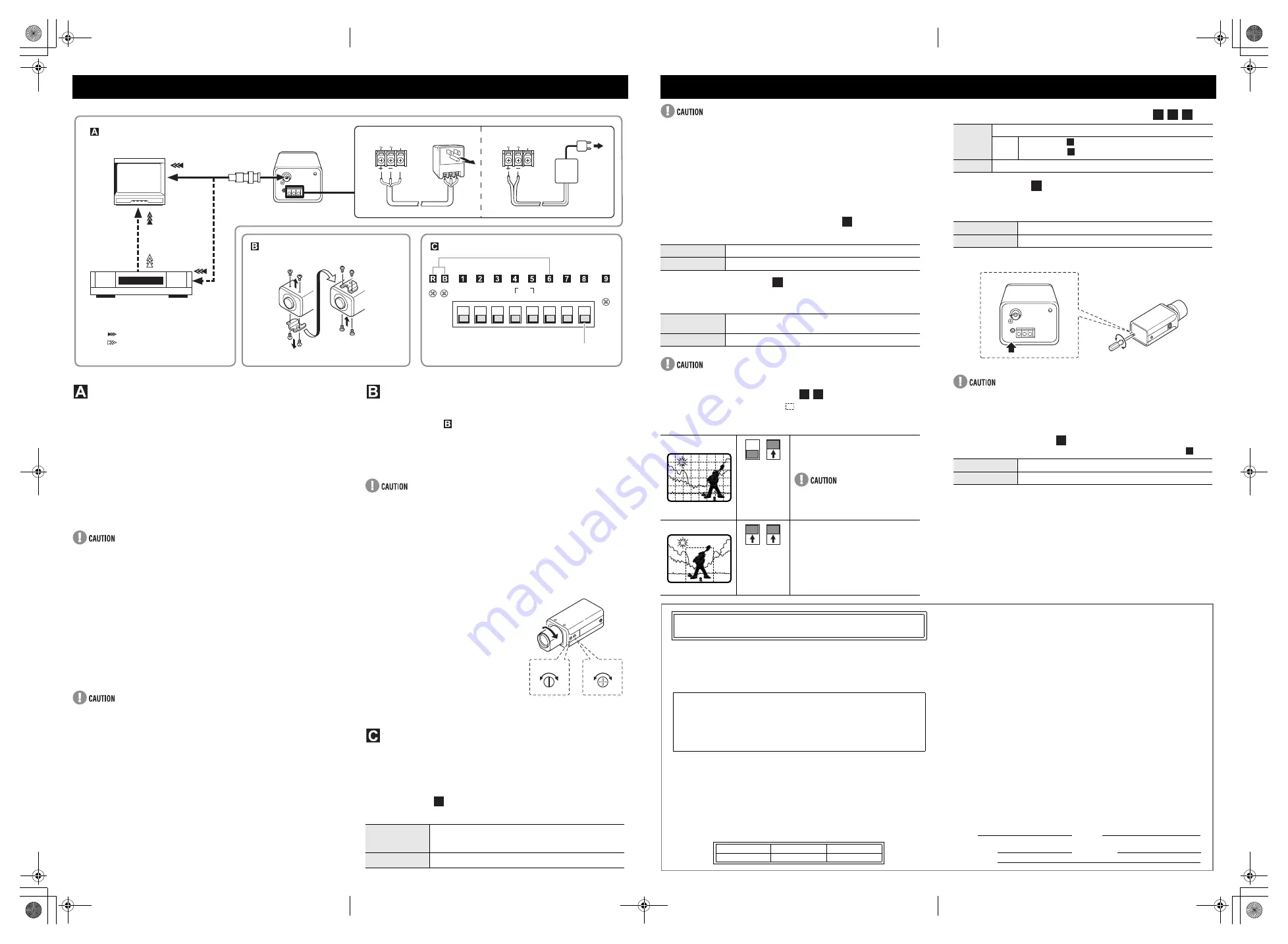
Making connections
1
Connect the camera and peripheral equipment.
2
Connect the power cable.
<When using a 24 V AC adapter>
Connect 3 wire grounded cable (use 18AWG+) as shown in Figure 1.
<When using a 12 V DC adapter>
Connect the cable as shown in Figure 2.
When connecting the power cable to the camera, check that the polarity
is correct.
To prevent a fire hazard use any UL listed wire rated VW-1 for the 24 V
AC cable input terminal.
3
Insert the power adapter plug into the wall outlet.
The power indicator (POWER) lights.
CAMERA INSTALLATION
Q
Camera attachment bracket
As shown in Figure above, you can remove the camera
attachment bracket and reattach it to the camera bottom if you want
to attach the camera to the top of an object. If you remove the
camera attachment bracket, be sure to use the removed screws
when reattaching it (other screws may not fit).
When using the camera attachment stand (sold separately), select a
location that will be able to withstand the weight of the camera and stand
for many years, and fix them securely in place.
Q
Flange-back adjustment
If the pick-up surface is not correctly positioned with relation to the lens
focal point, the picture will be out of focus (in particular when using auto-iris
power zoom lenses, sold separately). If that is the case, adjust the flange-
back position as described below.
1
Using a + screwdriver, loosen the
flange-back lock screw (M2:+).
2
Set the zoom lens to the maximum
telephoto position, and set the focus
using the focus ring on the lens.
3
Set the zoom lens to the maximum
wide angle position, and set the focus
using the flange-back adjustment
screw.
4
Repeat steps 2 and 3, until the image
stays in focus when changing from a
telephoto shot to a wide angle shot.
When the setting is complete, tighten the flange-back lock screw.
CAMERA ADJUSTMENTS/SETTINGS
The camera comes pre-adjusted and ready to install at time of factory
shipment, but you may want to make adjustments or settings to adapt to the
operating conditions or installation environment.
If you have trouble adjusting the camera, contact your place of purchase or
a Sanyo Authorized Service Center.
Q
Iris setting
Change Iris setting when using either lens below.
CONNECTIONS AND INSTALLATION
EI
HI
CENT
ON
MANU
LL
SHRP
AI
NORM NORM MULT
OFF
INT
ATW
IRIS
BLC
APER
WB
SYNC
NC
GAIN
IRIS
LEVEL
R
B
GND AC24V
DC12V
GND AC24V
DC12V
Connections
Monitor
Digital video recorder
or time-lapse VCR
: VIDEO IN
Camera installation
Camera screws (Shorter)
Camera adjustment/settings
Figure 2
Figure 1
24 V AC connection
3
3
2
1
12 V DC connection
3
2
: VIDEO OUT
NOT USED
Bracket screws (Longer)
EI
(for indoor use)
When using a manual or fixed iris lens and the electronic iris
function is on.
* Set the lens aperture to the shortest F stop.
AI
When using an auto-iris lens.
ADJ.
LOCK
2,3
3
1
4
1
The electronic iris is suitable for normal indoor use. When switch 1 (IRIS)
is set to the up (EI) position, do not use an auto-iris lens.
If used under fluorescent light, the image may flicker. In such a case,
change to incandescent lighting or set switch 1 (IRIS) to the down (AI)
position and use an auto-iris lens.
When shooting bright subjects, pay attention to the light angle in order to
avoid or minimize the smear effect.
If conditions are outside the electronic iris operation range or more than
the maximum illumination, the CCD will be saturated. In that case, use the
auto iris lens.
Q
Aperture (outline compensation)
If object outlines appear too strongly, set to “NORM”.
Q
Gain control (AGC)
For adjusting the sensitivity of the camera. Use this setting for shooting in
dark environments.
The HI setting causes noise generation and a grainy image.
Q
Backlight compensation
You can set the metering area (
), to have the lens iris adjust
automatically to make the image easy to see when the object is
backlit.
Q
White balance (color compensation)
Q
Sync setting
Vertical sync disturbance may occur when a selector is used to switch
between multiple cameras connected to one monitor. To prevent vertical
sync disturbance, set to “LL.”
LL (Line-Lock): Synchronizes the unit with power frequency.
If image disturbance doesn’t disappear after adjusting the PHASE dial on
the second and subsequent cameras, adjust the PHASE dial on the first
camera. If the problem persists, check that all the devices have been
connected with the correct power cable polarity.
Q
Iris dial (lens iris)
If the entire image is too dark or too bright, adjust the LEVEL dial (
).
ADJUSTMENT AND SETTINGS
SHRP
Emphasizes object outlines.
NORM
Normal setting
HI
Increased sensitivity allows shots to be taken in dark
environments.
NORM
Normal setting
When there
is backlight
in the entire
screen
Multi-spot metering
The screen is divided into 64 areas, and
each area is metered and backlight-
compensated.
If the background of the object is
extremely dark, the center of the object
may be too bright. In this case, set
center-weighted metering mode.
When there
is backlight
only in the
background
Center-weighted metering
Only the center of the image is metered
and backlight-compensated.
2
3
34 45
4 5
4 5
MANU
Lets you fine-tune the white balance manually.
WB
• R (Red) dial
: Turn clockwise to augment screen red.
• B (Blue) dial
: Turn clockwise to augment screen blue.
ATW
Compensation is performed automatically.
LL (external sync)
Adjust PHASE dial to eliminate sync disturbance.
INT (internal sync)
Internal Sync
Counterclockwise
Closes the lens iris, making the entire image darker.
Clockwise
Opens the lens iris, making the entire image brighter.
56 5
R 5
B
R
B
7
LINE
PHASE
59
9
OBLIGATIONS
In order to obtain warranty service, the product must be delivered to and picked up from an
Authorized Sanyo Service Center at the user's expense, unless specifically stated otherwise in
this warranty. The names and addresses of Authorized Sanyo Service Centers may be obtained
by calling the toll-free number listed below.
THIS WARRANTY IS VALID ONLY ON SANYO PRODUCTS PURCHASED OR RENTED IN
THE UNITED STATES OF AMERICA, EXCLUDING ALL U.S. TERRITORIES AND
PROTECTORATES. THIS WARRANTY APPLIES ONLY TO THE ORIGINAL RETAIL
PURCHASER OR END-USER. THE ORIGINAL DATED BILL OF SALE, SALES SLIP OR
RENTAL AGREEMENT MUST BE SUBMITTED TO THE AUTHORIZED SANYO SERVICE
CENTER AT THE TIME WARRANTY SERVICE IS REQUESTED.
Subject to the OBLIGATIONS above and EXCLUSIONS below, SANYO Fisher Company
warrants this SANYO product against defects in materials and workmanship for the periods
specified below. SFC will repair or replace (at its option) the product and any of its parts which fail
to conform to this warranty. The warranty period commences on the date the product was first
purchased or rented at retail.
SANYO INDUSTRIAL VIDEO
COLOR VIDEO CAMERA LIMITED WARRANTY
For product operation, authorized service center referral, service assistance or problem
resolution, call
CUSTOMER INFORMATION 1-800-421-5013
Weekdays 8:30 AM – 5:00 PM Pacific Time
For accessories and/or parts, call
PARTS ORDER INFORMATION 1-800-726-9662
Weekdays 8:30 AM – 5:00 PM Pacific Time
LABOR
PARTS
IMAGE DEVICE
3 YEARS
3 YEARS
3 YEARS
EXCLUSIONS
This warranty does not cover (A) the adjustment of customer-operated controls as explained in
the appropriate model's instruction manual, or (B) the repair of any product whose serial number
has been altered, defaced or removed.
This warranty shall not apply to the cabinet or cosmetic parts, batteries or routine maintenance.
This warranty does not apply to uncrating, setup, installation, removal of the product for repair or
reinstallation of the product after repair.
This warranty does not apply to repairs or replacements necessitated by any cause beyond the
control of SFC including, but not limited to, any malfunction, defect or failure caused by or resulting
from unauthorized service or parts, improper maintenance, operation contrary to furnished
instructions, shipping or transit accidents, modification or repair by the user, abuse, misuse,
neglect, accident, incorrect power line voltage, fire, flood or other Acts of God, or normal wear and
tear.
The foregoing is in lieu of all other expressed warranties and SFC does not assume or authorize
any party to assume for it any other obligation or liability.
SFC DISCLAIMS ALL OTHER WARRANTIES EXPRESS OR IMPLIED, WITH REGARD TO
THIS PRODUCT (INCLUDING THE WARRANTIES OF MERCHANTABILITY AND FITNESS). IN
NO EVENT SHALL SFC BE LIABLE FOR ANY SPECIAL, INCIDENTAL OR CONSEQUENTIAL
DAMAGES ARISING FROM THE OWNERSHIP OR USE OF THIS PRODUCT OR FOR ANY
DELAY IN THE PERFORMANCE OF ITS OBLIGATIONS UNDER THIS WARRANTY DUE TO
CAUSES BEYOND ITS CONTROL. SFC'S LIABILITY FOR ANY AND ALL LOSSES AND
DAMAGES RESULTING FROM ANY CAUSE WHATSOEVER, ARISING OUT OF OR IN
CONNECTION WITH THE SALE, USE OR OWNERSHIP OF THIS PRODUCT INCLUDING
WARRANTOR'S NEGLIGENCE, ALLEGED DAMAGED OR DEFECTIIVE GOODS, WHETHER
SUCH DEFECTS ARE DISCOVERABLE OR LATENT, SHALL IN NO EVENT EXCEED THE
PURCHASE PRICE OF THE PRODUCT.
ATTENTION
For your protection in the event of theft or loss of this product, please fill in the information below
for your own personal records.
Model No.
Serial No.
(Located on back or bottom side of unit.)
Date of Purchase
Purchase Price
Where Purchased
e_l53x4_us3_6.fm Page 2 Wednesday, July 30, 2003 11:30 AM


